Eureka AIR delivers breakthrough ideas for toughest innovation challenges, trusted by R&D personnel around the world.

Engine control apparatus

a technology of control apparatus and engine, which is applied in the direction of electric control, machines/engines, instruments, etc., can solve the problems of insufficient torque, difficult to achieve a vehicle which is provided with both, and inability to achieve excellent starting performance, etc., and achieve excellent driving performance.

Active Publication Date: 2013-01-08
SUBARU CORP
View PDF29 Cites 26 Cited by
  • Summary
  • Abstract
  • Description
  • Claims
  • Application Information

AI Technical Summary

Benefits of technology

[0011]One object of the present invention is to provide an engine control apparatus in a vehicle which one of a plurality of control modes can be selected, and achieves an excellent starting performance in any control mode without a feeling of excess or insufficient torque.
[0018]According to the aspects of the present invention, provided is a vehicle which is capable of selecting one of a plurality of engine modes with different engine output characteristics and which achieves an excellent driving performance without a feeling of excess or insufficient torque.

Problems solved by technology

Generally, a vehicle such as an automobile preferably has both excellent fuel economy performance and driving performance (acceleration response), but it is hard to achieve a vehicle which is provided with both of them.
However, in the above technologies disclosed in the documents, at a start of a vehicle, if a driver selects a control mode such as an economy mode in which an output is restricted to reduce fuel consumption, an engine of the vehicle is operated under a high load, so that a start of a vehicle on an upslope for example in an economy mode sometimes results in an insufficient torque, and an excellent starting performance cannot be attained.
On the other hand, if the driver selects a control mode such as a power mode for increasing output at the start of a vehicle, a slight depression of an accelerator pedal leads to a considerable change of a driving torque, so that a start of a vehicle on level ground for example in the power mode in which an engine of the vehicle is operated under a low load sometimes results in a shock of a sudden start for the driver due to a rapid acceleration.
In either mode at the start of a vehicle, an excellent driving performance cannot be attained.

Method used


Image

  • Engine control apparatus
  • Engine control apparatus
  • Engine control apparatus

Examples


first embodiment

[0059]The first embodiment is explained with reference to FIG. 1 through FIG. 14.

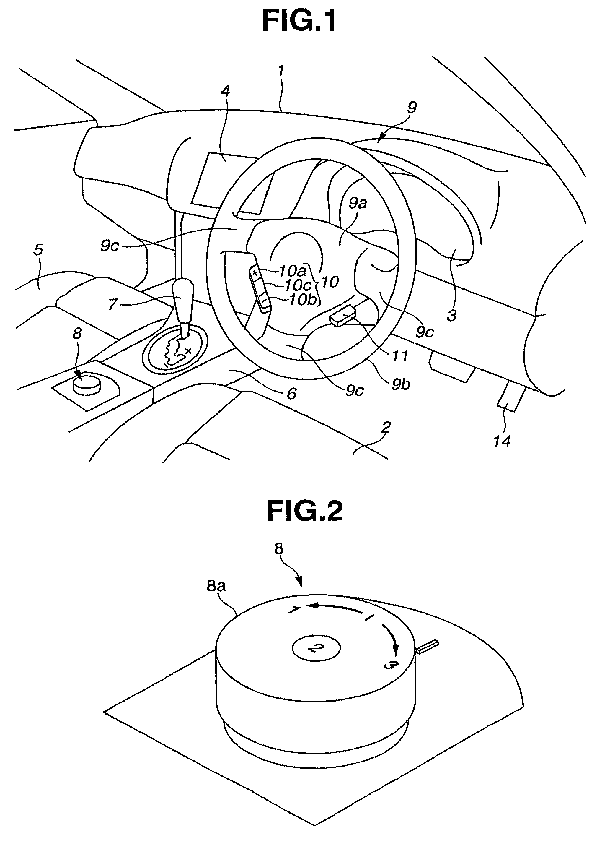
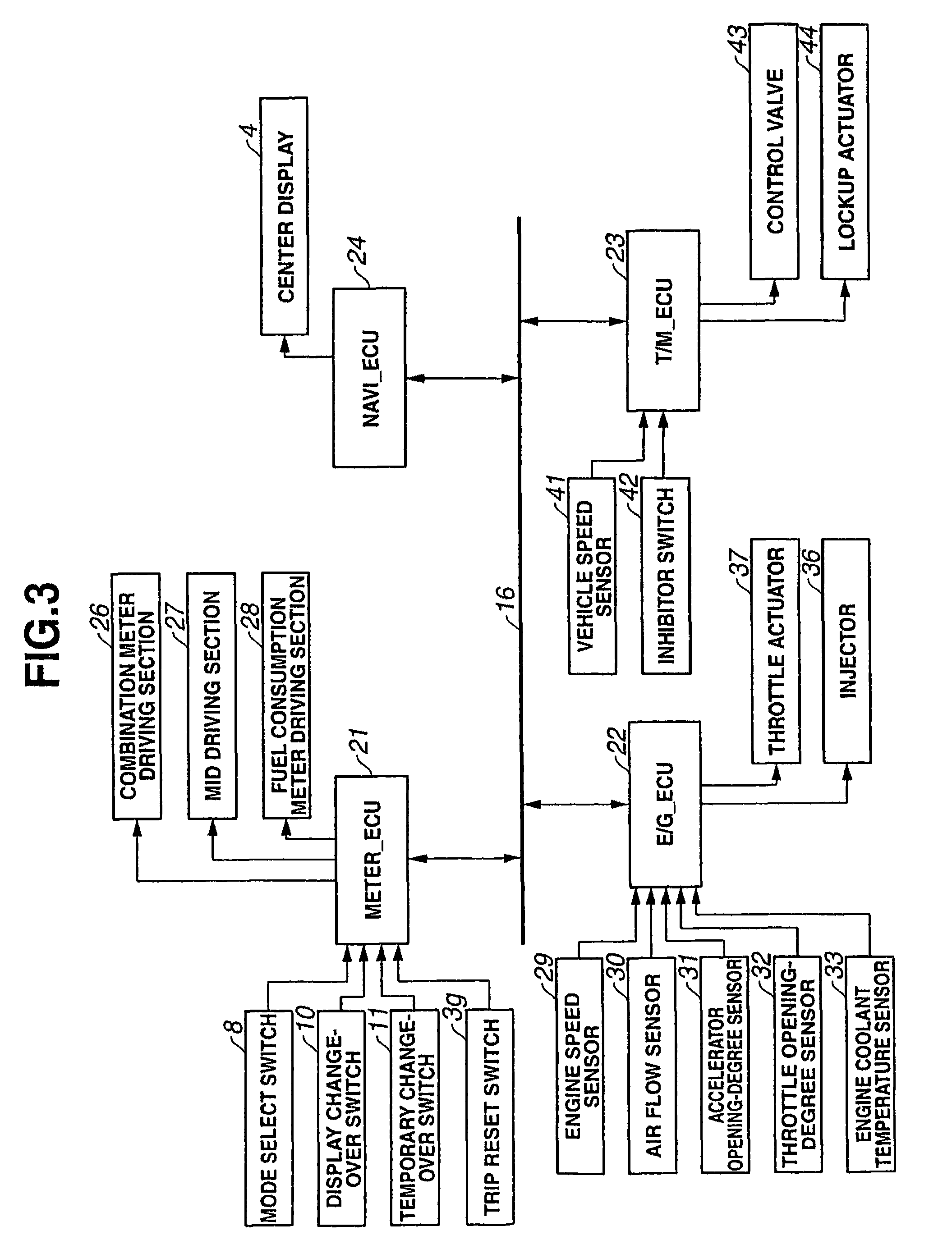
[0060]As shown in FIG. 1, an instrument panel 1 is provided to a front part in a room of a vehicle and extends in the width direction of the vehicle. The instrument panel 1 has a combination meter 3 at a position in front of a driver's seat 2. The instrument panel 1 also has a center display 4 for a known car navigation system at a central position thereof.

[0061]A center console 6 is disposed between the driver's seat 2 and a passenger's seat 5 and extends from the instrument panel 1 side toward the rear part of the vehicle body. The center console 6 is provided with a select lever 7 for selecting an automatic transmission range, and a mode select switch 8 at the rear of the select lever 7 for mainly selecting a driving power performance of an engine of the vehicle. A steering wheel 9 is further provided in front of the driver's seat 2.

[0062]The steering wheel 9 has a center pad portion 9a for housing a...

second embodiment

[0126]The present embodiment is a modification of the above described first embodiment, and the flowcharts shown in FIG. 12 and FIG. 13 are applied instead of the flowcharts shown in FIG. 6 and FIG. 7, while each of the mode maps shown in FIG. 14 are applied instead of the each of the mode maps shown in FIG. 8. Other configurations of the present embodiment are identical to those in the first embodiment, and will not be explained below.

[0127]In the above described first embodiment, in order to set a target throttle opening-degree θe, first, basic target torques TRQ1, TRQ2, and TRQ3 are set, and based on the basic target torques TRQ1, TRQ2, and TRQ3, a target torque τe is calculated. However, in the present embodiment, basic target throttle opening-degrees θα1, θα2, and θα3 are set instead of the basic target torques TRQ1, TRQ2, and TRQ3, and based on the basic target throttle opening-degrees θα1, θα2, and θα3, a target throttle opening-degree θe is calculated.

[0128]That is, in the e...

third embodiment

[0147]FIGS. 15 to 26 show a third embodiment of the present invention.

[0148]As shown in FIG. 15, an instrument panel 1 is provided to a front part in a room of a vehicle and extends in the width direction of the vehicle. The instrument panel 1 has a combination meter 3 at a position in front of a driver's seat 2. The instrument panel 1 also has a center display 4 for a known car navigation system at a central position thereof.

[0149]A center console 6 is disposed between the driver's seat 2 and a passenger's seat 5 and extends from the instrument panel 1 side toward the rear part of the vehicle body. The center console 6 is provided with a select lever 7 for selecting an automatic transmission range, and a mode select switch 8 at the rear of the select lever 7 for mainly selecting a driving power performance of an engine of the vehicle. Furthermore, a control mode change switch 46 is provided at the side of the mode select switch 8.

[0150]A select gate 15 includes an automatic transmi...


PUM


Abstract

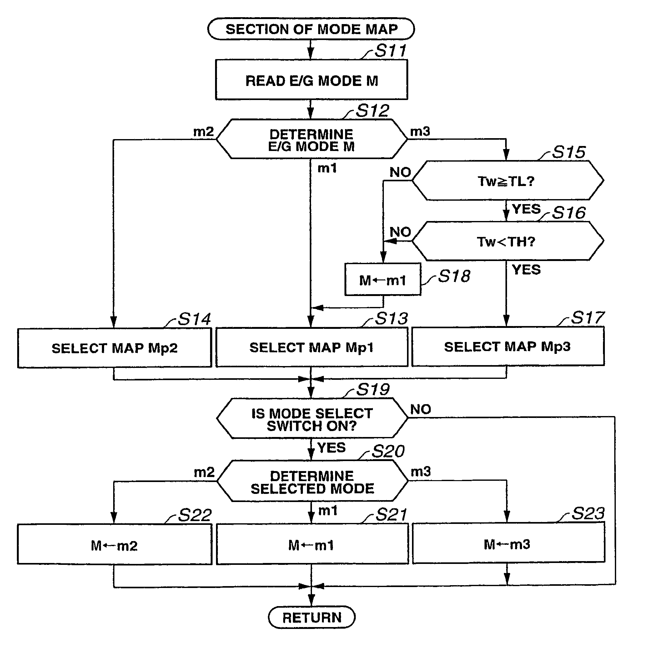
A storage unit provided in an engine control device stores three kinds of mode maps having different engine output characteristics. One of the mode maps is selected in accordance with the driving conditions, and a target torque is set by referring to the selected mode map using an engine speed and an accelerator opening-degree as parameters. A throttle opening-degree signal corresponding to the target torque is output to a throttle actuator, and an operation of opening or closing the throttle valve is performed in response to the throttle opening-degree signal.

Description

CROSS REFERENCE TO RELATED APPLICATIONS[0001]This application is a continuation-in-part of U.S. application Ser. No. 11 / 802,175 filed on May 21, 2007 now U.S. Pat. No. 7,487,033 which claims benefit of Japanese Application No. 2006-142138 filed on May 22, 2006, and U.S. application Ser. No. 11 / 783,265 filed on Apr. 6, 2007 now U.S. Pat. No. 7,424,361 which claims benefit of Japanese Applications No. 2006-106146 filed on Apr. 7, 2006 and No. 2006-140754 filed on May 19, 2006, the entire contents of which are incorporated herein by their reference.BACKGROUND OF THE INVENTION[0002]1. Field of the Invention[0003]The present invention relates to an engine control apparatus having engine control modes including at least a high output mode and an output restricted mode.[0004]2. Description Related Art Statement[0005]Generally, a vehicle such as an automobile preferably has both excellent fuel economy performance and driving performance (acceleration response), but it is hard to achieve a v...

Claims


Application Information

Patent Timeline
Patent Type & Authority Patents(United States)
IPC IPC(8): G06F19/00G06G7/70
CPCF02D11/105F02D41/021F02D41/2422F02D2200/501F02D2200/604F02D2250/18
Inventor HIJIKATA, KENJI
Owner SUBARU CORP
Why Eureka
Eureka Blog
Learn More