
Wellbore casing mounted device for determination of fracture geometry and method for using same

a technology of fracture geometry and mounting device, which is applied in the direction of borehole/well accessories, instruments, survey, etc., can solve the problems of high cost, high risk of oil exploration and development, and inability to give reliable data connected to the length of the fracture propped, etc., and achieve the effect of low loss signal transport mechanism

Active Publication Date: 2013-01-15
HEXION INC
View PDF11 Cites 10 Cited by
  • Summary
  • Abstract
  • Description
  • Claims
  • Application Information

AI Technical Summary

Benefits of technology

Enables precise measurement of propped fracture geometry, including length, height, and azimuth, even in harsh down-hole environments, improving the assessment of well productivity and hydraulic fracturing effectiveness.

Problems solved by technology

Oil exploration and developing oil wells often pose great financial risks because the costs are substantial.
This results in a pressure build up until such pressure exceeds the strength of the formation rock.
Currently there are logging techniques that give limited information on fracture height, but virtually no technique that gives any reliable data connected to propped fracture length.
The lack of an accurate assessment of propped fracture length is due to a combination of factors.
First and foremost is the fact that propped fractures can extend for hundreds of feet away from the wellbore.
Secondly, the down-hole conditions (in particular temperature and pressure) encountered by logging equipment limited the electronic equipment that could be used, types of signals that could be generated and the type of data gathered by this type equipment.
However, current logging devices do not address all critical data requirements and more sophisticated equipment may not stand up well to the environmental conditions of a borehole.
For example, temperatures may exceed 200° C. down-hole, and this type of heat limits the electronic sensors and circuits that can be used in a logging device.
However, as mentioned previously, there is limited data available on fracture height and virtually no method available to accurately measure an extended propped fracture length.

Method used


Image

  • Wellbore casing mounted device for determination of fracture geometry and method for using same
  • Wellbore casing mounted device for determination of fracture geometry and method for using same
  • Wellbore casing mounted device for determination of fracture geometry and method for using same

Examples


example 1

10 GHz Prototype Design and Testing

Equipment

[0184]An embodiment of the invention was tested with the components that would be down-hole tested in an oven at temperatures from 20 to 210° C.

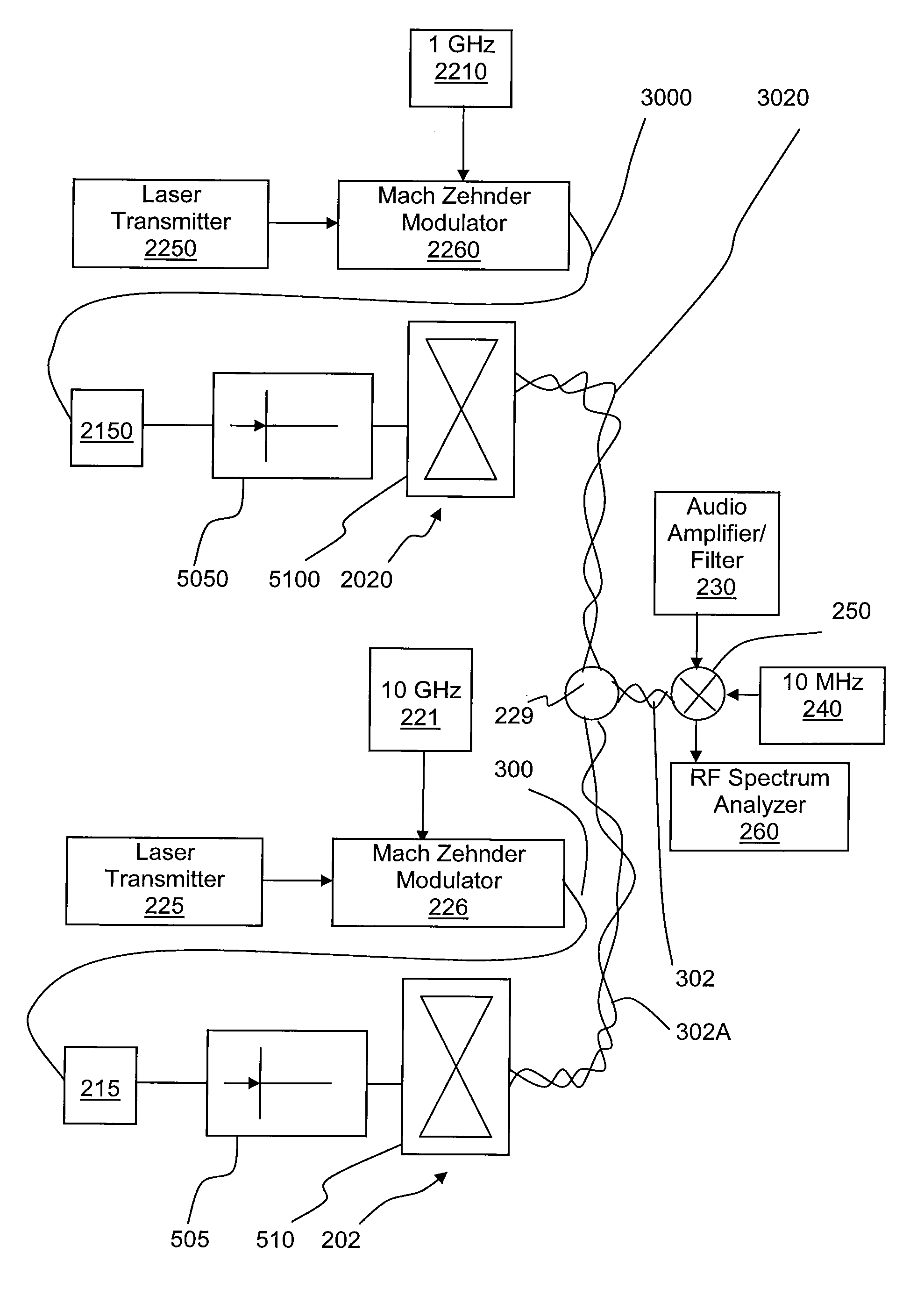
[0185]The test apparatus had the components shown in FIG. 3A and was used to measure the distance of the moving blades of a fan (not shown). Thus, the embodiment employed in this example included a microwave signal source (microwave frequency generator) 221, a laser driver (laser transmitter) 225, a modulator 226, an audio amplifier / filter 230, mixer 250, microwave frequency generator 240 and RF spectrum analyzer 260, as well as a photodiode 505 and transceiver 510. The modulator 226 was connected to the photodiode 505 by 1 kilometer of polyimide coated fiber 300. The transceiver 510 was connected to the audio amp / filter 230 by a twisted pair of wires 302 (shown in FIG. 3A). Also, in the example a DC bias was applied to the photodiode 505 through a twisted pair (not shown). A DC bias source and som...

example 2

Propagation Experiments

[0218]The system of Example 1 was designed to operate at 10 GHz with a free space wavelength of 3 cm. This short wavelength was chosen to facilitate a 24 mm form factor on the down-hole receiver and antenna.

[0219]However, it was desired to learn about the electrical properties of various proppant that could be introduced into a subterranean fracture. The real and imaginary dielectric constant of such proppants influences the electromagnetic guiding properties of the fracture. This information, as well as the size of the casing, assists in choosing an optimum operating frequency.

[0220]Thus, after completing the 10 GHz prototype design and testing, the propagation loss in a few sample proppant materials was measured (understanding the optimal frequency may not be exactly 10 GHz).

[0221]The propagation experiment example was set up as follows. Two known lengths of 5 cm inside diameter Polyvinyl Chloride (PVC) pipe were capped at both ends after being filled with p...

example 3

[0242]This example used a simulated fracture sandstone model to perform propagation tests with proppants to determine the optimal operational frequencies to be used in fracture length detection. The test frequency range used was from 250 MHz to 3 GHz. Sand and CERAMAX proppants were used in the sandstone test.

[0243]FIG. 11A shows the electronics setup for the propagation test. Antennas 600, 601 are placed in the slots within the braces and surrounded by foam encapsulated by the plywood structure. Two antennas 600, 601 were used in the tests. Transmitting antennas (601) were placed at different locations as shown in FIG. 11A. The microwave network analyzer 620 was used to generate signals ranging from 250 MHz to 3 GHz. As shown in FIG. 11A, the attenuation of the signal was measured by comparing the received signal level at the receiving antenna (element 600) as the transmitting antenna (element 601) was changed.

[0244]The network analyzer 620 generates a signal in the frequency range...


PUM


Abstract

A logging system and method for measuring propped fractures and down-hole subterranean formation conditions including: a radar source; an optical source; an optical modulator for modulating an optical signal from the optical source according to a signal from the radar source; a photodiode for converting the modulated optical signal output from the optical modulator to the source radar signal. A transmitter and receiver unit receives the source radar signal from the photodiode and transmits the source radar signal via at least one antenna attached to the casing and in communication with at least one photodiode into the formation and receives a reflected radar signal. A mixer mixes the reflected radar signal with the source radar signal to provide an output. This can describe fractures connected to the wellbore and differentiate between the dimensions of the two vertical wings of a propped fracture.

Description

FIELD OF THE INVENTION[0001]The present device relates to logging radar devices functionally attached to (or integral with) the casing. More particularly, the present invention relates to radar systems that use electromagnetic wave propagation to locate and identify geometry aspects of proppant packed fractures created in geological structures located in the ground, wherein at least a portion of the operation occurs in a borehole (also known as “down-hole” as referred to in the art).BACKGROUND OF THE INVENTION[0002]Oil exploration and developing oil wells often pose great financial risks because the costs are substantial. To mitigate some of the financial risks, logging has become essential in nearly every phase of exploration as well as drilling, completing, and producing the well. Logging techniques provide information on the depth of formations, the presence of oil, the bottom-hole or formation temperature as well as data associated to the success of completion techniques, initia...

Claims


Application Information

Patent Timeline
Patent Type & Authority Patents(United States)
IPC IPC(8): G01V3/00
CPCE21B43/267E21B47/01E21B49/00
Inventor MCDANIEL, ROBERT R.SHERIFF, MICHAEL L.FUNK, ERIC E.FUNK, ETHAN A.
Owner HEXION INC
Learn More