Method and apparatus for improved tread splicing

a technology of retreaded tires and cutting processes, applied in the direction of non-skid devices, transportation and packaging, other domestic objects, etc., can solve the problems of inaccurate manual intervention in the cutting process of the length of the tread to provide a substantially uninterrupted tread pattern around the entire periphery of the retreaded tire, increase the difficulty of such procedures, and increase the variability of retreaded tire performance and bonding characteristics. , to achieve the effect of efficient and cost-effective,

Active Publication Date: 2013-01-22
BRIDGESTONE BANDAG LLC
View PDF35 Cites 4 Cited by
  • Summary
  • Abstract
  • Description
  • Claims
  • Application Information

AI Technical Summary

Benefits of technology

[0011]In one aspect, the disclosure describes a method of cutting a length of precured tread for the construction of a retread tire, which includes a tire casing having a layer of cushion gum applied thereto. The method includes measuring a circumference of the tire casing and cushion gum, and dispensing a length of tire tread from a roll based on the measured circumference. The length of tire tread relative to a tread cutter is adjusted so that the tire tread design may be spliced to provide a continuous pattern. The points where the precured tread may be cut are generally located between a set of marks formed in precured tread. The marks provide locations where the cut of the tread will permit for formation of a continuous tread pattern across the ultimate splice and also provide for improved performance and bonding. For example, the marks permit consistent cutting and splicing along tread profiles that improve, among other things, the bonding characteristics and the performance characteristics. The marks permit for pre-evaluated location determination taking into consideration the operational characteristic of the retreaded tire and the process by which it is constructed. The marks include areas of variation or tolerance that provide for the variability in operation without substantially adversely affecting the ultimate retreaded tire and process of construction.
[0012]In certain embodiments, more than one set of marks may be provided. The invention provides marks that may be differentiated thereby facilitating greater flexibility in the cutting, especially when considered in the varying circumferential measurements of the tire casing assemblies. The result is a significant improvement in the final retreaded tire, its performance, the bonding procedure during manufacture, etc. Furthermore, the invention removes variation, unpredictability, and waste from prior operations.

Problems solved by technology

The complication and difficulty of such procedures is increased because the tread patterns are subject to varying characteristics depending on the cut location.
In previously proposed retreading machines and operations, variability in the measurements of the circumference of the casing or of the dispensed length of tread all too often resulted in dimensional variations when cutting the length of tread.
Manual intervention in the cutting process of the length of tread to provide a substantially uninterrupted tread pattern around the entire periphery of the retreaded tire is not only inaccurate, but also compounds the dimensional variability in determining the appropriate length of tread that is required.
Such intervention often fails to account for the characteristics of the cross-sectional tread and improving the characteristics of the abutting ends of the tread for performance and bonding characteristics.
The inaccuracy of the manual cutting operation in matching the tread pattern may adversely affect the service life and aesthetic appeal of the final retreaded tire.
In certain instances, the compounded variability in cutting the appropriate length of tread may make the length of tread unsuitable for use on a retreaded tire, thus necessitating the cutting of an additional length.
Such rework operations are time consuming, increase the cost of the retreading operation, increase waste, and so forth.

Method used


Image

  • Method and apparatus for improved tread splicing
  • Method and apparatus for improved tread splicing
  • Method and apparatus for improved tread splicing

Examples


Embodiment Construction

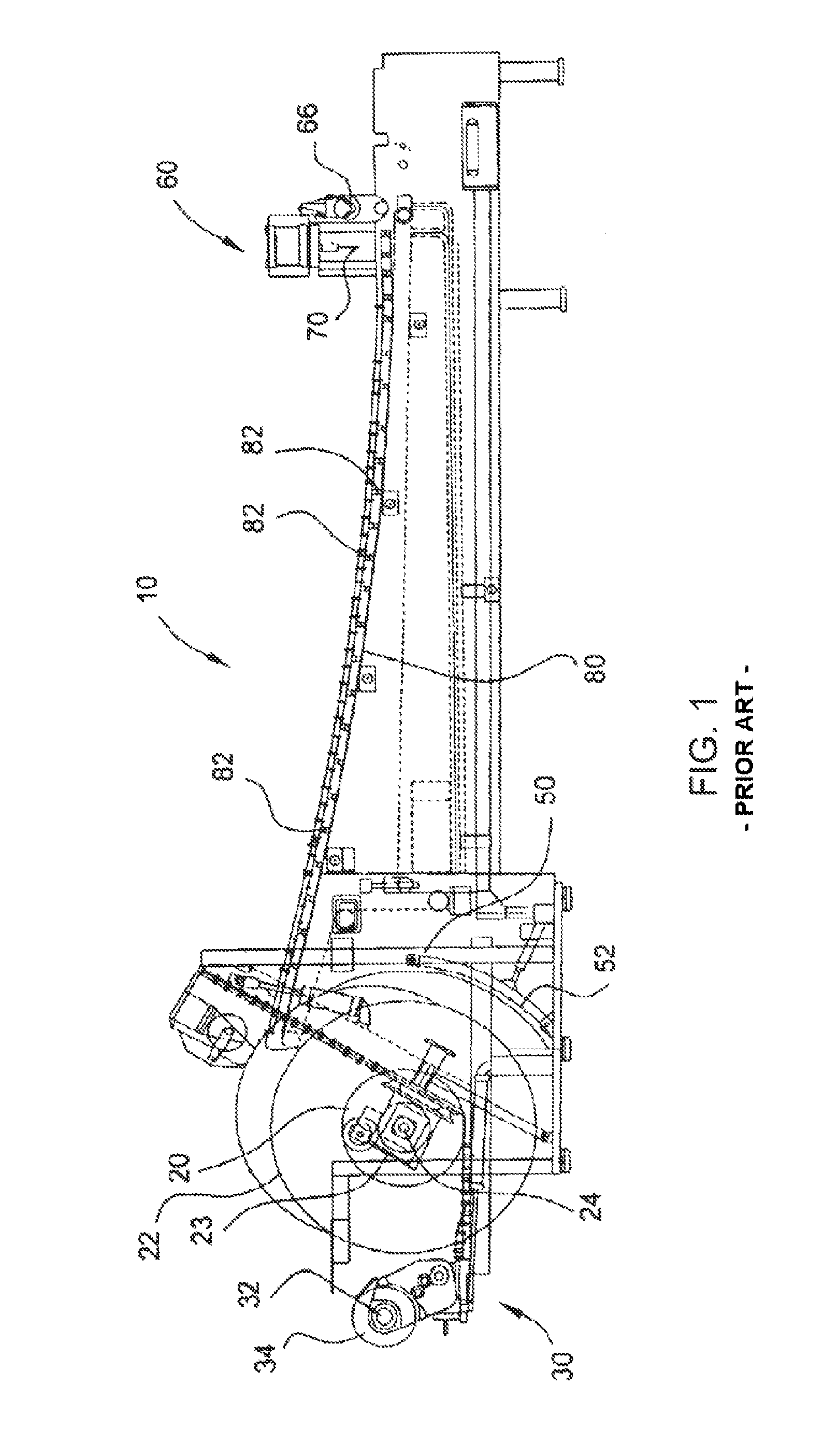
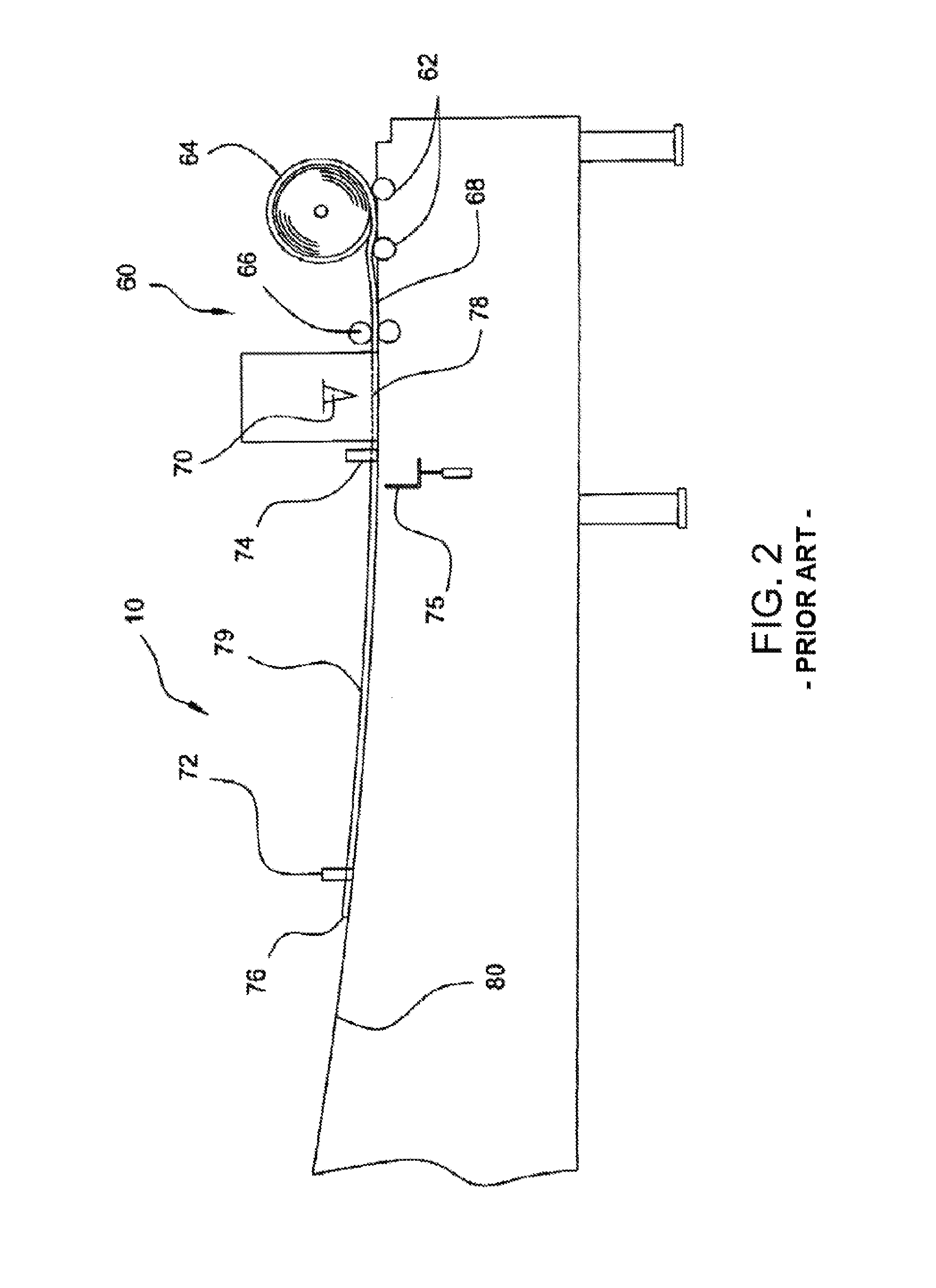
[0023]A retreading machine or integrated tire bench 10 is shown from a side view in FIG. 1, and a detailed view thereof is shown in FIG. 2. In the illustrated example, the tire bench 10 is a semi-automated retread tire building apparatus configured to assemble retread tires. The tire bench 10 includes a rotatable hub 20 for mounting a tire casing thereon, and a cushion gum applicator system 30 having a spindle 32. A roll of cushion gum 34 may be mounted on the spindle 32 and dispensed onto a tire casing 22 mounted on hub 20.

[0024]The tire bench 10 may include a device for measuring the circumference of the casing 22 mounted thereon. In the illustrated example, a measurement wheel 50 is provided on a measurement arm 52. Measurement arm 52 is pivotable by actuation, for example, through a pneumatic cylinder, to engage a surface (either a tire casing, or cushion gum applied to a tire casing). Measurement wheel 50 rotates when it comes into contact with the periphery of the rotating tir...


PUM

PropertyMeasurementUnit
lengthaaaaaaaaaa
circumferenceaaaaaaaaaa
cut lengthaaaaaaaaaa

Abstract

A method of cutting a length of tire tread for a retread tire includes measuring a circumference of the tire casing and cushion gum, and dispensing a length of tire tread from a roll based on the measured circumference. The length of tire tread relative to a tread cutter is adjusted so that the tire tread design at the point where the tread may be cut is between a set of marks formed in the periodically repeating tread design. The tread is then cut along a linear length of the tread disposed within the marks so that the periodically repeating tread pattern appears substantially continuous across a seam defined when the section of tire tread is wrapped around the casing such that the first and second ends meet in abutting relationship.

Description

BACKGROUND OF THE INVENTION[0001]The invention relates generally to a method and apparatus for making retreaded tires and, more particularly, to a method of and apparatus in which preformed treads may be consistently cut to lengths that provide for improved splicing while maintaining continuous and repeatable patterns across varying retreading conditions.[0002]Retreaded tires provide an economical way to gain additional use from tire casings after the original tread or retread has become worn. According to a conventional method of retreading, sometimes referred to as cold process retreading, worn tire tread on a used tire is removed to create a buffed, generally smooth treadless surface about the circumference of the tire casing to which a new layer of tread may be bonded.[0003]The tire casing is then typically inspected for injuries, some of which may be skived and filled with a repair gum while others may be severe enough to warrant rejection of the casing. After completion of the...

Claims


Application Information

Patent Timeline
Patent Type & Authority Patents(United States)
IPC IPC(8): B29D30/54
CPCB60C11/12B29D30/54Y10T428/2457Y10T156/1066B29D30/56B29D30/52B29D30/68
Inventor CERNY, ANDY
Owner BRIDGESTONE BANDAG LLC
Why Eureka
Try Eureka