Protective device

a protective device and a technology of a protective device, applied in the direction of containers, tray containers, packaged goods, etc., can solve the problem that the design cannot be applied in principle, and achieve the effect of cost-effective and simple construction of the protective devi

Active Publication Date: 2013-01-29
STABILA MESSGERATE GUSTAV ULLRICH GMBH & CO KG
View PDF29 Cites 38 Cited by
  • Summary
  • Abstract
  • Description
  • Claims
  • Application Information

AI Technical Summary

Benefits of technology

[0007]The objective of the present invention is to further develop a protective device of the initially described type, which offers a sufficient shock protection, whereas it is als

Problems solved by technology

These designs can only then be applied in princip

Method used


Image

  • Protective device
  • Protective device
  • Protective device

Examples


Embodiment Construction

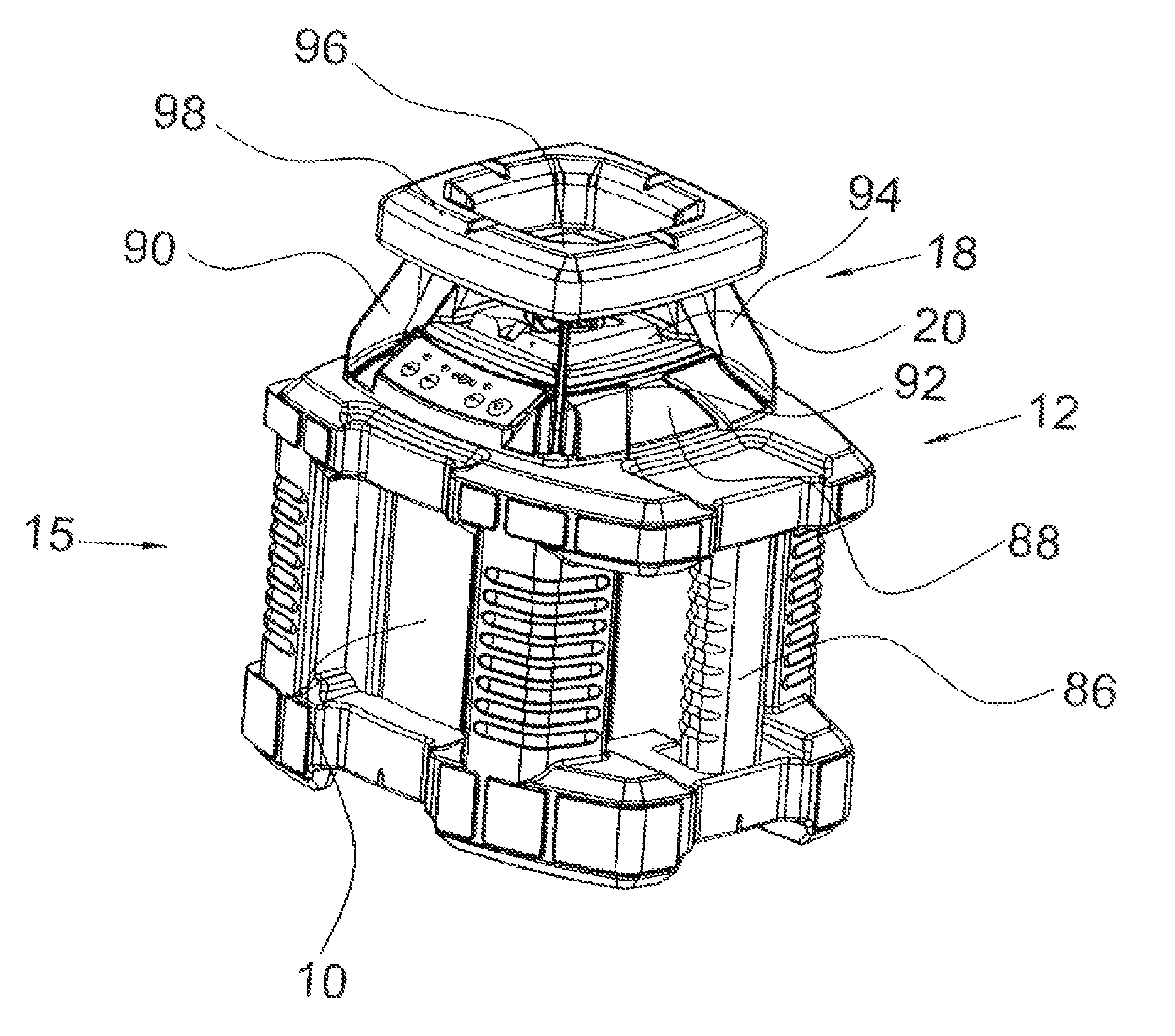
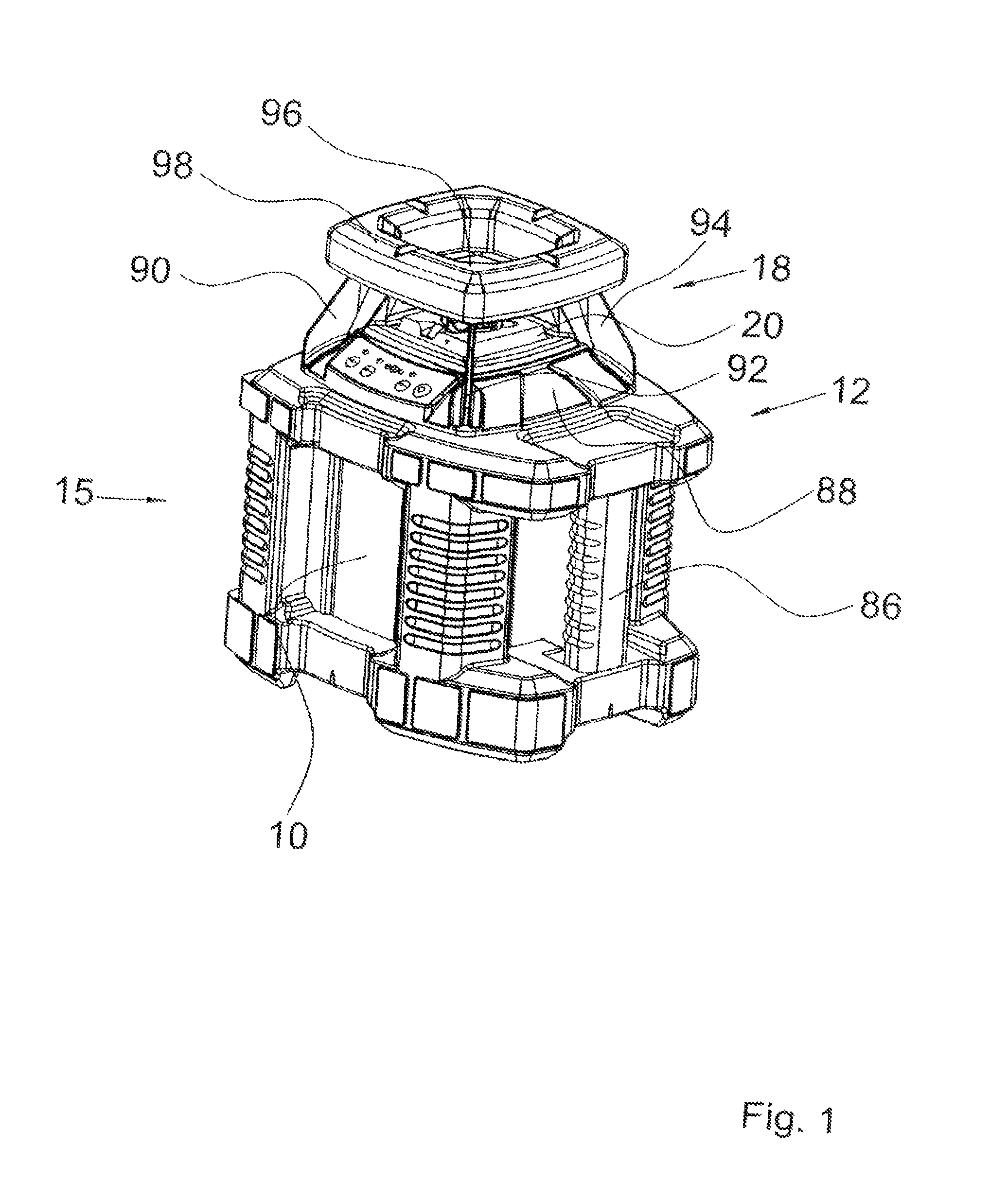
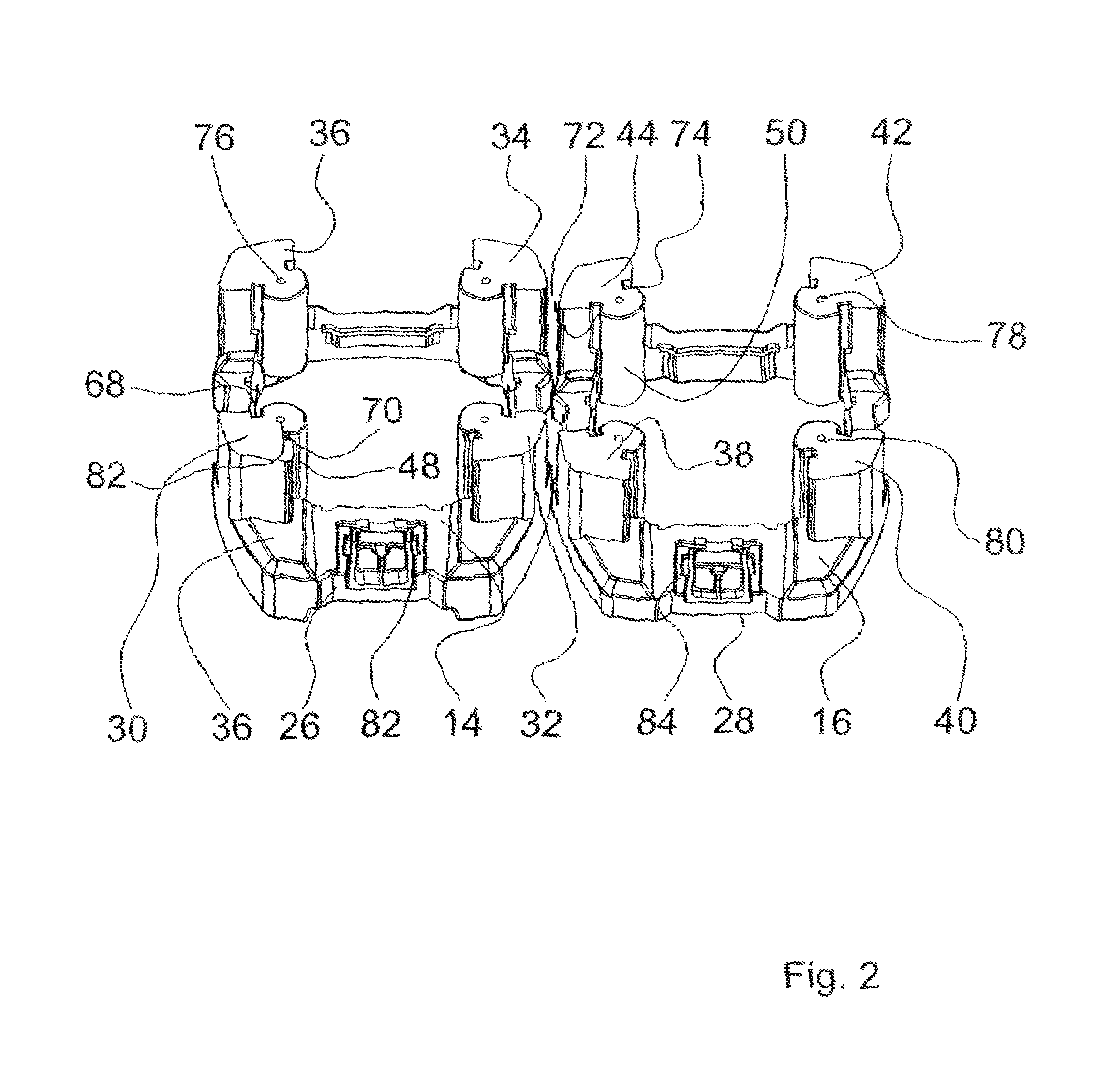
[0032]The premise on which the invention is based is explained in FIGS. 1 through 7 by means of a protective housing 12, which encloses a laser instrument 10, without being limited therein. Rather, the premise based on the invention applies to any protective housings, which should preferably enclose those instruments that are susceptible to shock. This particularly includes measuring devices.

[0033]The invention pertains in general to a protective device for a housing, whereby the protective device must only enclose the housing partially. Thus it is possible, that the protective device may consist of corner elements, which are supported by the corners of the housing and are connected with each other in a manner that is described in the following.

[0034]In the variant of FIGS. 1 through 7, the protective housing 12 consists of a two-part base part 15 as well as an attachment 18, which encloses the laser emission optic 20. The attachment 18 is, however, not a required characteristic. It...


PUM


Abstract

A protective device made of plastic, which is intended as an instrument housing for a measuring instrument. In order to ensure sufficient shock protection, which assures that the protective device is not damaged by hard shocks, the protective device is assembled from a core which is made of thermoplastic material and at least in sections encloses the housing, and a sheathing, which is made particularly of rubber elastic material.

Description

BACKGROUND OF THE INVENTION[0001]The invention pertains to a protective device made of plastic, which is intended as a housing, such as an instrument housing. The invention especially pertains to a protective housing, which, at least in part, encloses an instrument housing, preferably a measuring device, such as laser equipment, and at least in sections consists of plastic.[0002]A protective housing for a laser level is known from DE-U-200 21 781. The laser instrument is completely enclosed by the protective housing and consists of plastic material. In order to use the laser instrument, the protective housing must be opened and the laser instrument be placed on an outer surface of the protective housing.[0003]In order to protect the laser instrument, its instrument housing is enclosed by a protective housing, which is designated as a receptacle according to EP-B-1 376 055. The protective housing has U-shaped metal brackets, which can be covered in sections with shock absorbing plast...

Claims


Application Information

Patent Timeline
IPC IPC(8): B65D85/00B65D81/02B65D85/38
CPCG01C15/004F16P1/02
Inventor KALLABIS, GABRIEL
Owner STABILA MESSGERATE GUSTAV ULLRICH GMBH & CO KG
Why Eureka
Try Eureka