High precision corrosion monitoring sensor assembly and system

a sensor and high-precision technology, applied in the field of petrochemical pipelines, can solve the problems of de-bonding or compromising an epoxy bond between the transducer (or delay line) and the pipe without additional support, and achieve the effect of larger and more accurate transducers

Active Publication Date: 2013-02-05
SAUDI ARABIAN OIL CO +1
View PDF30 Cites 18 Cited by
  • Summary
  • Abstract
  • Description
  • Claims
  • Application Information

AI Technical Summary

Benefits of technology

[0009]Embodiments of the present invention provide an enhanced clamping fixture referred to as a transducer hold-down fixture (THDF) allowing the permanent installation of a highly accurate 5-MHz-10-MHz transducer having a delay line (approximately 15 mm in additional stack height) attached thereto to improve the accuracy of the readings at the transducer. The lateral forces acting upon the transducer due to environmental factors in the field, in particular with respect to the height of the transducer and the attached delay line, are likely to compromise or de-bond an epoxy bond between the transducer (or delay line) and the pipe without additional support. Embodiments of the present invention provide a THDF having two additional bonding points on the pipe and a structure having sufficient rigidity to maintain the mounting location of the transducer with a high degree of precision.
[0010]Embodiments of the present invention provide a rigid structure that not only accommodates the shape of such highly accurate transducers and attached delay lines, but also is adjustable to accommodate installation on pipes having any diameter selected from a range of diameters. For example, embodiments of the present invention provide a rigid THDF that mounts to a pipe having an outer diameter greater than or equal to six (6) inches, including a flat surface (“the diameter range”). With reference to FIG. 4, the critical dimensions can be shown for providing a THDF having the level of adjustability for accommodating the transducers described herein, including a delay line, throughout the diameter range. Embodiments of the present invention are adjustable so that, regardless of the diameter of the pipe on which it is installed, the rigidity of the THDF and the forces applied by the THDF to the pipe are constant throughout the diameter range. Because embodiments of the present invention are both rigid and adjustable, and because the rigidity of the THDF and the forces applied thereby to the pipe are constant throughout the diameter range, the THDF allows the transducer to provide measurements with minimal error attributable to any flex or change in the configuration of the THDF due to pipe size or due to environmental factors, such as temperature.
[0011]Because embodiments of the present invention are less vulnerable to external lateral forces to de-bond the transducer, and because embodiments of the present invention allow permanent and precise positioning of the transducer at a pinpoint location, embodiments of the present invention reduce the need for personnel to routinely access the installation location for maintenance or readjustment of the assembly. Accordingly, embodiments of the present invention can be more efficiently installed at locations having inconvenient access or locations that are regularly inaccessible (such as when excavation or scaffolding is required). For example, where embodiments of the present invention are installed at 20 pipeline locations, annual savings in ongoing scaffolding and excavation costs for OSI programs can be approximately $25,000. Moreover, embodiments provide a THDF having a small footprint that minimizes the amount of excavation or scaffolding required to mount the THDF to the pipe.
[0012]Further, the accuracy and precision of measurements provided by embodiments of the present invention allow embodiments of the present invention to be employed in continuous monitoring operations where such real-time measurements can be used to ascertain corrosion rates with high fidelity, such as in controlling the injection dosage of corrosion inhibitors added to crude oil.

Problems solved by technology

The lateral forces acting upon the transducer due to environmental factors in the field, in particular with respect to the height of the transducer and the attached delay line, are likely to compromise or de-bond an epoxy bond between the transducer (or delay line) and the pipe without additional support.

Method used


Image

  • High precision corrosion monitoring sensor assembly and system
  • High precision corrosion monitoring sensor assembly and system
  • High precision corrosion monitoring sensor assembly and system

Examples


Embodiment Construction

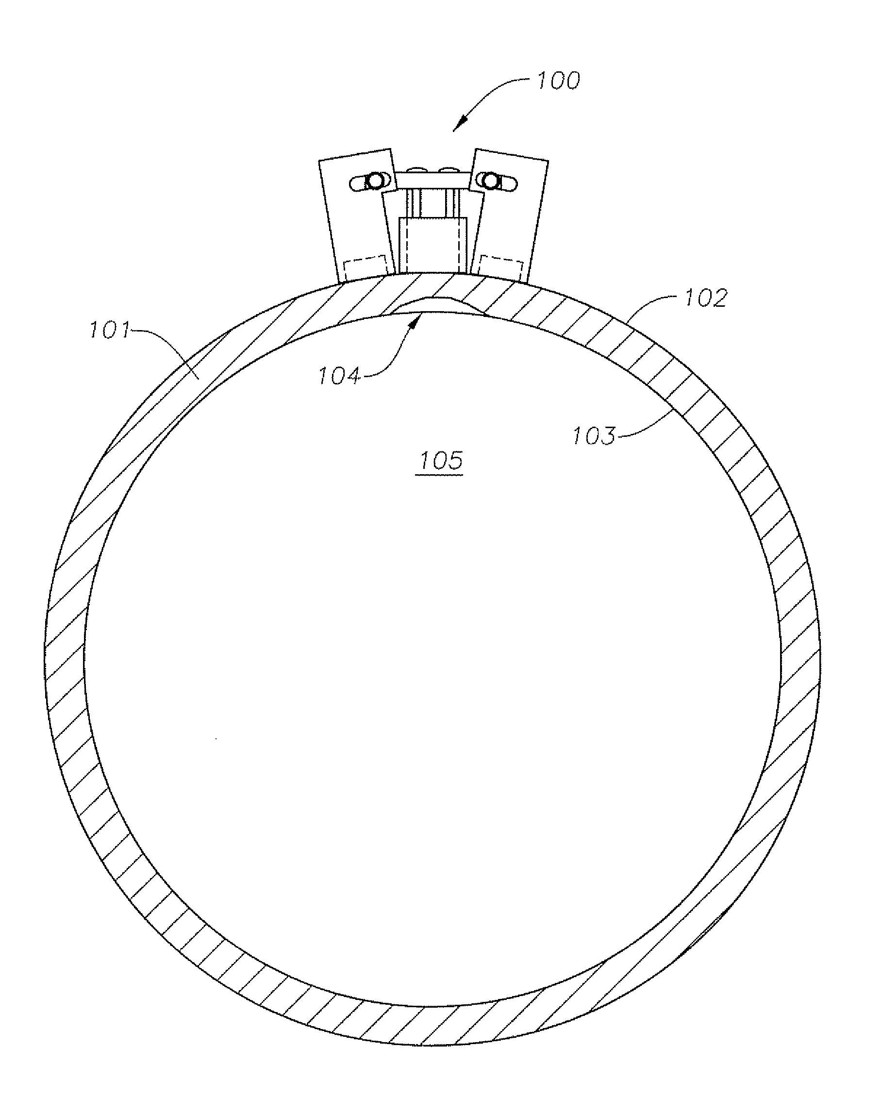
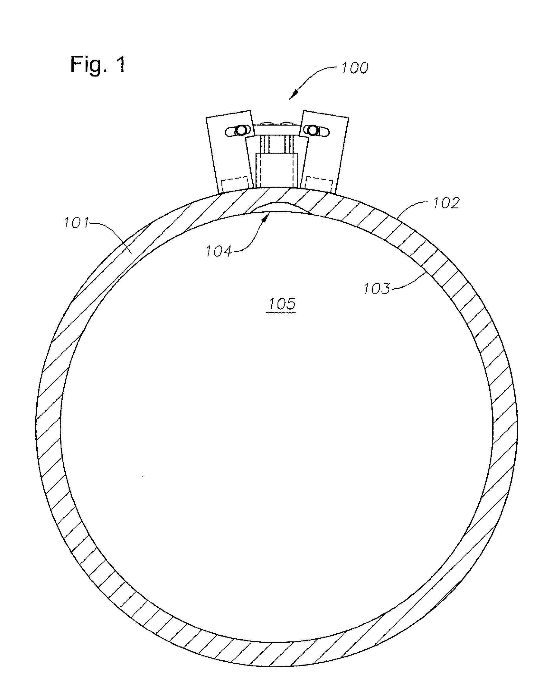
[0036]So that continuous wall thickness monitoring can be performed at precise location of a pipeline, a pipe, or a vessel, an embodiment of the present invention, as can be shown with reference to FIG. 1, provides a high-precision corrosion monitoring assembly 100 (HPCM) to be permanently mounted on an outer wall of the pipeline, pipe, or vessel, for example, as on outer pipe wall 102 of pipe 101. The monitoring assembly 100 may be referred to herein as the HPCM or as an “HPCM sensor” or an “HPCM assembly.” With reference to FIG. 10, an HPCM 100 according to embodiments of the present invention is shown mounted to a pipe 101. Although embodiments of the present invention are described with respect to a “pipe” herein, the invention is not limited to such embodiments and can also be used with respect to other types of vessels, including those having flat surfaces.

[0037]The permanent mounting of the HPCM 100 allows for consistent measurements in multiple measurement cycles over a peri...


PUM

PropertyMeasurementUnit
diameteraaaaaaaaaa
lengthaaaaaaaaaa
heightaaaaaaaaaa

Abstract

A high-precision corrosion monitoring sensor assembly is provided for permanent mounting on a vessel to measure wall thickness of the vessel. The assembly includes an ultrasonic transducer and a delay line, which are bonded to the vessel wall a first location. The assembly is further bonded to the vessel by an adjustable fixture. The assembly includes a cross-member attached to the ultrasonic transducer, having a pivot pin at each distal end. The pivot pins are attached to a first tower and a second tower, which bond to the outer vessel wall at a second location and a third location. The position of the first and second towers can be adjusted with respect to angle and placement about the pivot pins. Fasteners are attached to the pivot pins and can be tightened to make rigid the fixture, thereby allowing configuration of the assembly for use on flat surfaces and small-diameter pipes.

Description

BACKGROUND OF THE INVENTION[0001]1. Area of the Invention[0002]The invention relates generally to the field of petrochemical pipelines and, in particular, to the field of electronic detection and monitoring of corrosion in petrochemical pipelines.[0003]2. Description of the Related Art[0004]Pipelines in petrochemical industries are often susceptible to damage caused by excessive corrosion. The life expectancy of a pipe before failure mostly depends on the chemical and physical properties of transported gaseous or liquid media, the environmental condition surrounding the pipe and a suitable cathodic protection (CP) system which prevents anodic behavior leading to metal loss. In some cases, only certain locations of pipes are exposed to considerable corrosion. If such corrosion in pipes is not detected and monitored, it can lead to damage, failure, and spills, which can result in undesirable consequences including monetary loss, safety hazards, and environmental damage. Accordingly, r...

Claims


Application Information

Patent Timeline
Patent Type & Authority Patents(United States)
IPC IPC(8): G01N29/04
CPCG01B17/02G01N29/043G01N29/2468G01N29/46G01N29/2481G01B2210/58G01N2291/2634G01N2291/02854G01N2291/044G01N2291/101
Inventor MINACHI, ALIAL-SUBAII, GHAZZAY M.SALEH, AYEDH S.LAICHE, ERIKALIGHT, GLENN
Owner SAUDI ARABIAN OIL CO
Why Eureka
Try Eureka