
Green waste water pump station control system

a technology of pump station and control system, which is applied in the direction of pump control, positive displacement liquid engine, pump control, etc., can solve the problems of sanitary sewer overflow and raw sewage discharge into the environment, insufficient power supply for pump station, and constant increase of energy cost to power pump station, so as to reduce the dependence on foreign oil, reduce the cost of energy and maintenance for pump station running, and reduce the effect of wear and tear

Active Publication Date: 2013-02-12
MEHR NASSER FRED
View PDF7 Cites 17 Cited by
  • Summary
  • Abstract
  • Description
  • Claims
  • Application Information

AI Technical Summary

Benefits of technology

The invention is a control system for submerged pumps used in a waste water pump station. The system minimizes energy usage and maintenance costs, reduces greenhouse gases, and encourages the use of domestic energy sources. The system includes multiple pumps that rotate in a specific order to avoid excessive wear and tear. The control system can also provide redundancy in case of failure, and create jobs through retrofitting existing pump stations.

Problems solved by technology

If this is insufficient, or in the case of failure of the pumping station, a backup in the sewer system can occur, leading to a sanitary sewer overflow and the discharge of raw sewage into the environment.
The storage volume of the wet well between the ‘pump on’ and ‘pump off’ settings is designed to minimize pump starts and stops, but not enough to enable the pump to run continuously.
The continual rise of energy costs to power the pumps has strained municipal and state budgets at a time when revenues have fallen.
Infrastructure maintenance competes for tax dollars and is often put off as budget cutting is forced.

Method used


Image

  • Green waste water pump station control system
  • Green waste water pump station control system
  • Green waste water pump station control system

Examples


Embodiment Construction

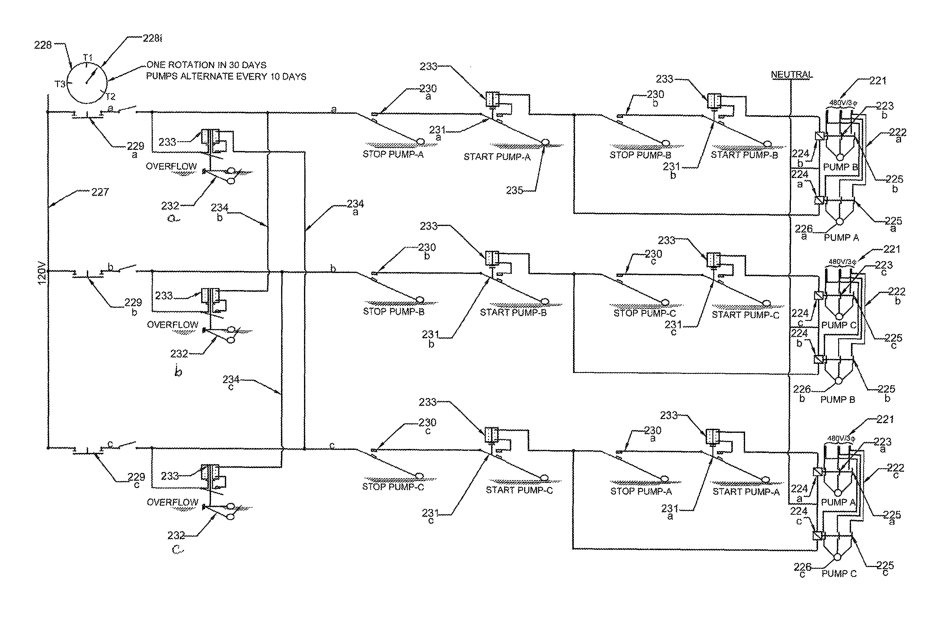
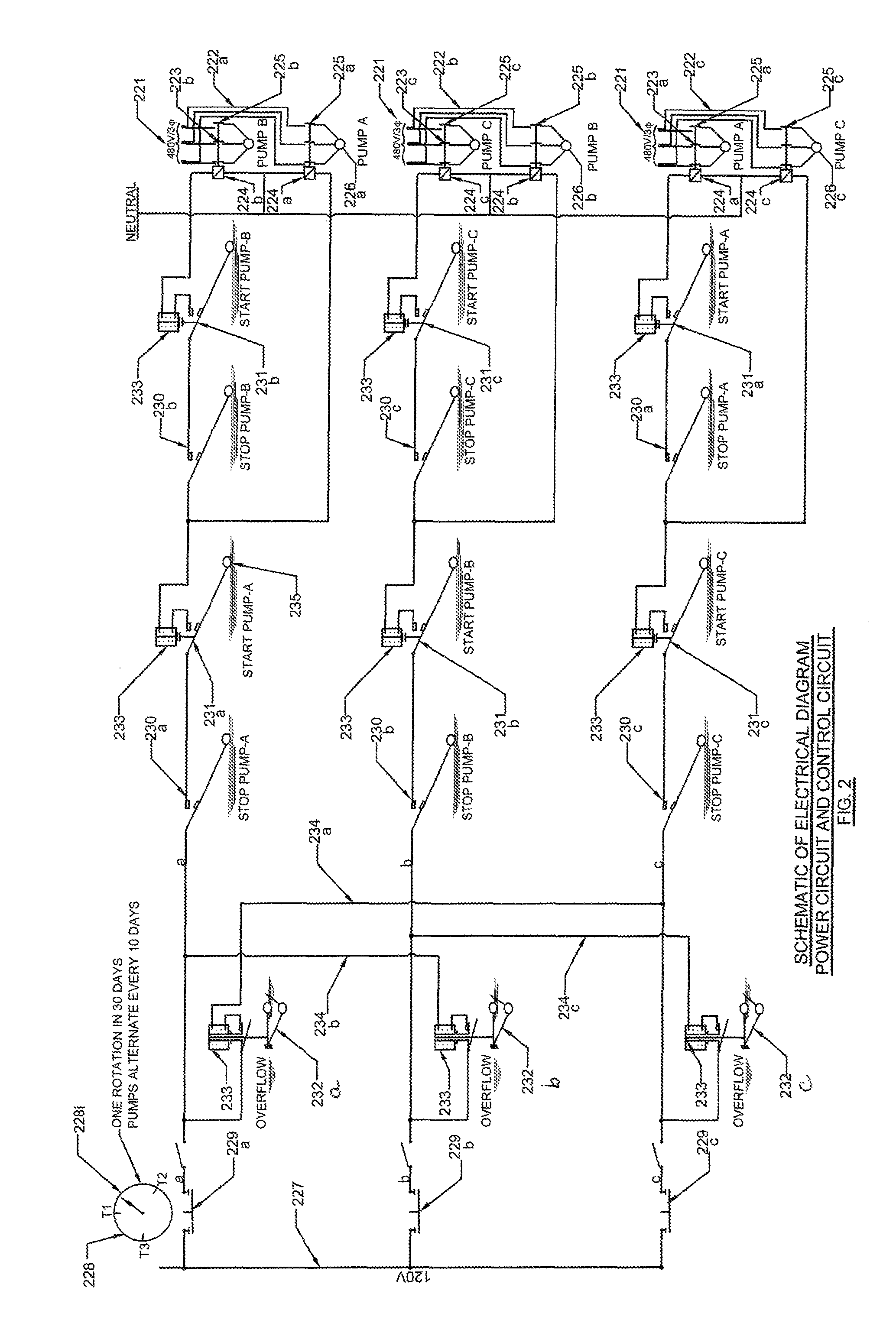
[0011]This invention is the control method for green lift stations with three or more submerged pumps whereby the primary pump runs continuously. The specific embodiment shown in FIG. 2 relates to the control panel that operates a pump station under the Energy Saving Green Waste Water Pump Station Design concept (patent pending application Ser. No. 13 / 335,908). Further the embodiment shown in FIG. 3 relates to the float switch levels of a three pump lift station. The number of pumps in a lift station can be increased and the sequence of operation of this invention can be adapted to accommodate additional pumps as will be explained herein.

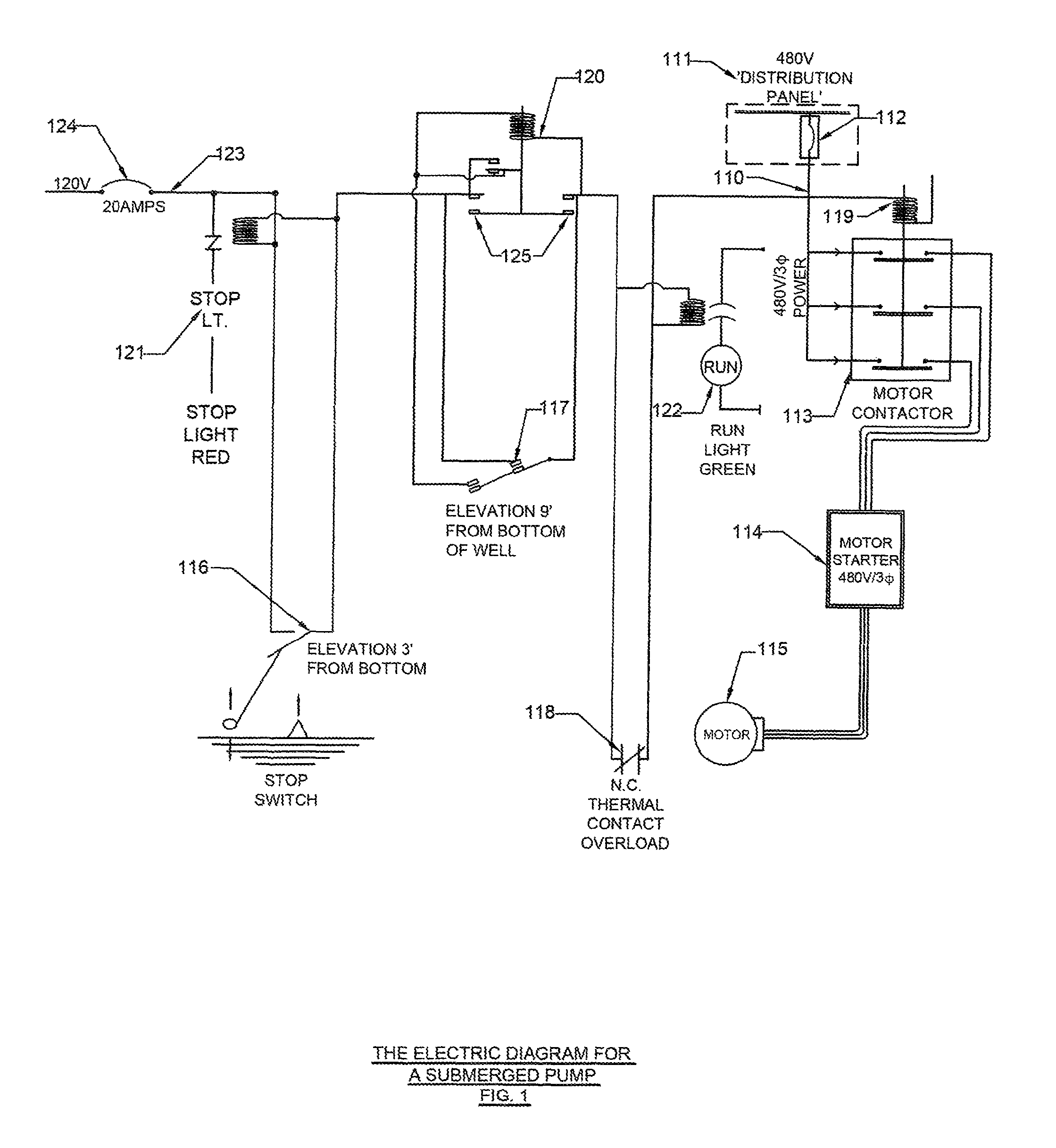
[0012]For better understanding of the control system in the Energy Saving Green Waste Water Pump Station Design, it is beneficial to first explain the operation of control of a submerged pump. FIG. 1 provides the electrical diagram operation of a submerged pump. In FIG. 1, there are two electrical circuits that are powered from two separate power so...


PUM


Abstract

An electrical control system for energy efficient pump stations providing for continuous operation of a single primary pump with a second pump functioning as the support pump and a third pump acting as the standby / emergency pump. All pumps are of equal horsepower and horsepower selection is determined by the system curve to select the lowest, most efficient horsepower necessary to discharge water at the highest inflow rate while not allowing the water level to drop below the submerged pump level during continuous running of the primary pump. A timer having an indicator arm rotates one full revolution every thirty days changing the pump sequence to reduce wear and tear on individual pumps. Each pump functions as the primary, secondary and backup / emergency pump for the same number of hours during the monthly cycle. Adding control circuits enables one or more pumps to be added when necessary.

Description

CROSS REFERENCE TO RELATED APPLICATION[0001]The invention of this Control System is unique as it is designed to control the operation of the pumps as presented in the Energy Saving Green Waste Water Pump Station Design concept (patent pending application Ser. No. 13 / 335,908).BACKGROUND OF THE INVENTION[0002]Pumping stations in sewage collection systems, also called lift stations, are normally designed to handle raw sewage that is fed from underground gravity pipelines (pipes that are laid at an angle so that a liquid can flow in one direction under gravity). Sewage is fed into and stored in an underground pit, commonly known as a wet well. The well is equipped with electrical instrumentation to detect the level of sewage present. When the sewage level rises to a predetermined point, a pump will be started to lift the sewage upward through a pressurized pipe system called a sewer force main from where the sewage is discharged into a gravity manhole. From here the cycle starts all ove...

Claims


Application Information

Patent Timeline
IPC IPC(8): F04B41/06F04B49/04
CPCF04B47/06F04D15/0218F04D15/029F04B49/04
Inventor MEHR, NASSER FRED
Owner MEHR NASSER FRED
Learn More