
Method for connecting thick-walled metal workpieces by welding

Active Publication Date: 2013-02-12
V&M DEUT GMBH
View PDF13 Cites 6 Cited by
  • Summary
  • Abstract
  • Description
  • Claims
  • Application Information

AI Technical Summary

Benefits of technology

The patent text explains about laser beam welding of pipes and how it is being improved by reducing the seam cross section and cutting welding times. The text also mentions that providing a surface for the laser to highly reflect its irradiation can make a big difference in the welding process. The technical effect of this is to improve the efficiency and quality of laser beam welding of pipes.

Problems solved by technology

There was, however, a drawback that the seam preparations and tolerances, required for laser beam welding, could not be reconciled with the constraints during implementation of pipe strings for laying pipelines.
This could not be exploited heretofore, however, as a result of the tolerance requirements during production of pipelines.
A drawback of this method is the need for an additional workpiece which has to be conformed to the respective notch configuration.
As a result, manufacturing time is increased and thus the production costs of the pipe connection.
These welding methods are disadvantageous because of the very small welding rate.
In view of the described tolerance demands of a connection of thick-walled pipes by laser welding and as a consequence of the still unresolved problem to realize with technically viable and efficient laser power a qualitatively reliable and efficient weld joint with a minimal number of welded regions and weld layers, the welding of thick-walled workpieces, like e.g. of pipes, by laser or hybrid laser methods has not gained any relevance to date.
The application of laser beam welding has been further shown to be economically disadvantageous because about 15-20% of the introduced laser power can no longer be made available for the actual welding process as a result of the transmission of laser beams through the joined gap.
As of yet, the known laser welding processes could not meet these demands.

Method used


Image

  • Method for connecting thick-walled metal workpieces by welding
  • Method for connecting thick-walled metal workpieces by welding
  • Method for connecting thick-walled metal workpieces by welding

Examples


Embodiment Construction

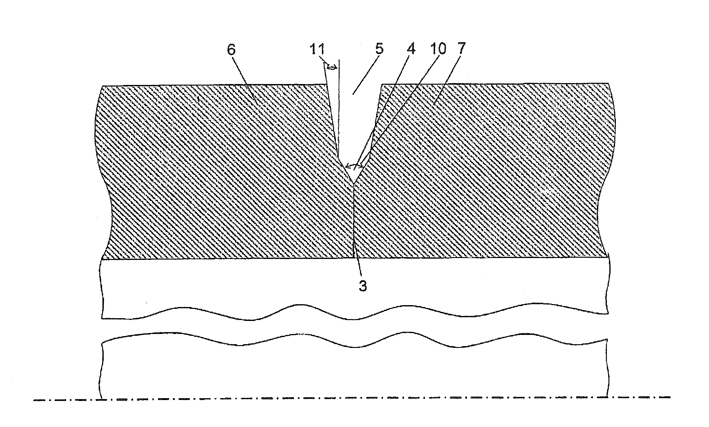
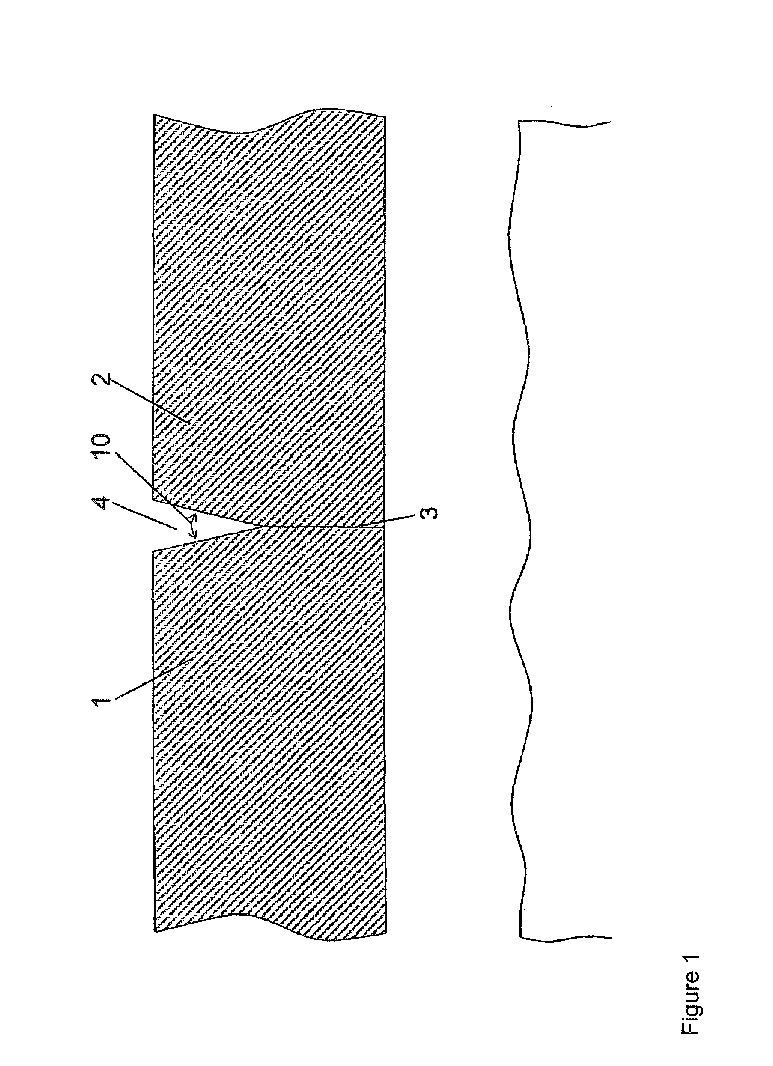
[0060]FIG. 1 shows the basic configuration of the weld regions and the seam preparation as Y-seam for the method according to the invention for welding thick-walled pipes in the wall thickness range of 8 to 15 mm with two weld regions.

[0061]Depicted are portions of pipes 1, 2 which are provided in the first weld region (root position) with an I joint as seam preparation 3, with the gap being close to zero in this case.

[0062]At first laser beam welding or hybrid laser arc welding is used for the root position in gap-dependent manner, with the hybrid laser arc welding involving preferably MIG welding as part of the process in addition to laser welding.

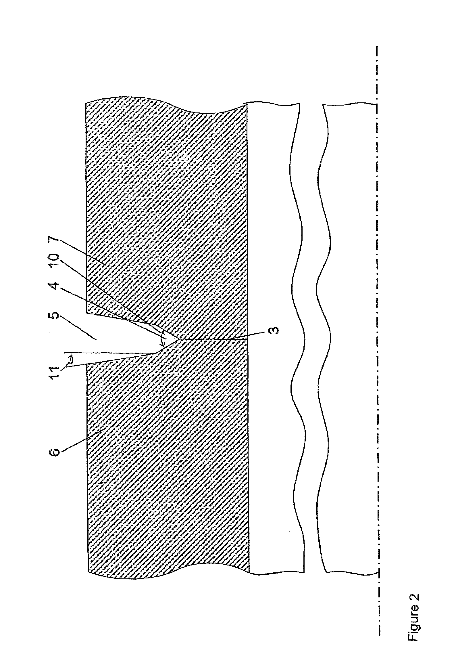
[0063]When wall thicknesses between 8 and 15 mm are involved, the weld joint is realized preferably with only two weld regions, each with a weld layer, with the second layer serving as filling layer. In order to attain a fill connection of the pipe cross section at high weld rate, the seam preparation 4 for the second weld region is prov...


PUM

PropertyMeasurementUnit
Lengthaaaaaaaaaa
Lengthaaaaaaaaaa
Lengthaaaaaaaaaa

Abstract

The invention relates to a method for connecting thick-walled metal workpieces by welding. In order to create the weld joint, the cross-sections are provided with a maximum of three weld regions according to wall thickness, the welding being carried out by a combined use of welding methods: the first weld region (root) is welded by means of laser beam welding or hybrid laser-arc welding, the second weld region is welded by means of hybrid laser-arc welding, and the third weld region required occasionally depending on the thickness of the sheet metal is welded by means of hybrid laser-arc welding or simply arc welding. The invention also relates to a seam preparation corresponding to the respective welding method used.

Description

CROSS-REFERENCES TO RELATED APPLICATIONS[0001]This application is the U.S. National Stage of International Application No. PCT / DE2008 / 001063, filed Jun. 26, 2008, which designated the United States and has been published as International Publication No. WO 2009 / 000259 and which claims the priorities of German Patent Applications, Serial No. 10 2007 030 050.8, filed Jun. 26, 2007, and Serial No. 10 2008 029 724.0, filed Jun. 24, 2008, pursuant to 35 U.S.C. 119(a)-(d).[0002]The invention relates to a method for connecting thick-walled metal workpieces by welding, in particular of pipes of steel, as well as to a device for carrying out the method.[0003]In addition to the connection of pipes, the welding method according to the invention is equally applicable for example for connecting thick-walled metal sheets or hollow sections of varying thicknesses and cross sections or for connecting penetrations of pipes of hollow sections.[0004]In particular, the invention relates to pipes with w...

Claims


Application Information

Patent Timeline
IPC IPC(8): B23K31/02
CPCB23K9/0282B23K26/285B23K33/006B23K26/282B23K26/348
Inventor KEITEL, STEFFENNEUBERT, JANSCHELLER, WOLFGANGLIEDTKE, MARKUSCAESAR, CHRISTIAN
Owner V&M DEUT GMBH
Learn More