Spindle head device and machine tool

a spindle head and machine tool technology, applied in the direction of attachable milling devices, chucks, manufacturing tools, etc., can solve the problems of wear of the shank receiving recess of the spindle nose, increased equipment cost, and complicated maintenance and management, so as to prevent the increase of equipment cost and prevent the development of complicated maintenance and management.

Active Publication Date: 2013-02-19
CITIZEN WATCH CO LTD
View PDF15 Cites 6 Cited by
  • Summary
  • Abstract
  • Description
  • Claims
  • Application Information

AI Technical Summary

Benefits of technology

[0008]It is an object of the present invention to provide a spindle head device installed in a machine tool, which is a multipurpose type capable of stably retaining, in an exchangeable manner, several types of tool holders provided with shanks mutually different in terms of mechanical structures, on a common spindle by tool retaining mechanisms corresponding respectively to the tool holders, and thus capable of preventing equipment cost from increasing and maintenance and management from becoming complicated.
[0009]It is another object of the present invention to provide a spindle head device installed in a machine tool, which can eliminate the need of replacing or renewal of a spindle even when a shank receiving recess for receiving a shank of a tool holder is worn, and thus can prevent maintenance cost from increasing.
[0010]It is still another object of the present invention to provide a general-purpose machine tool which includes a spindle head device capable of stably retaining, in an exchangeable manner, several types of tool holders provided with shanks mutually different in terms of mechanical structures, on a common spindle by tool retaining mechanisms corresponding respectively to the tool holders, and which can thereby prevent equipment cost from increasing and maintenance and management from becoming complicated.
[0011]It is a still further object of the present invention to provide a machine tool which can eliminate the need of replacing or renewal of a spindle even when a shank receiving recess provided in a spindle head device for receiving a shank of a tool holder is worn, and thus can prevent maintenance cost from increasing.

Problems solved by technology

Therefore, in this case, equipment cost may increase, and maintenance and management may be complicated.
Therefore, repeated tool-changing works may cause a wear of the shank receiving recess of the spindle nose, and in such a case, the spindle needs to be replaced with new one.
In this connection, the spindle is usually required to be machined in high precision at the inner surface thereof including the shank receiving recess and the outer surface thereof adapted to be fitted into a bearing unit, and in recent years, there is an increasing requirement of forming a fluid passage for supplying cleaning fluid or cooling fluid so as to penetrate through the spindle, so that the spindle has now become relatively expensive among all components of a machine tool.
Therefore, if the tool-changing is frequently carried out, the replacement of such an expensive spindle with new one may result higher maintenance costs.

Method used


Image

  • Spindle head device and machine tool
  • Spindle head device and machine tool
  • Spindle head device and machine tool

Examples


first embodiment

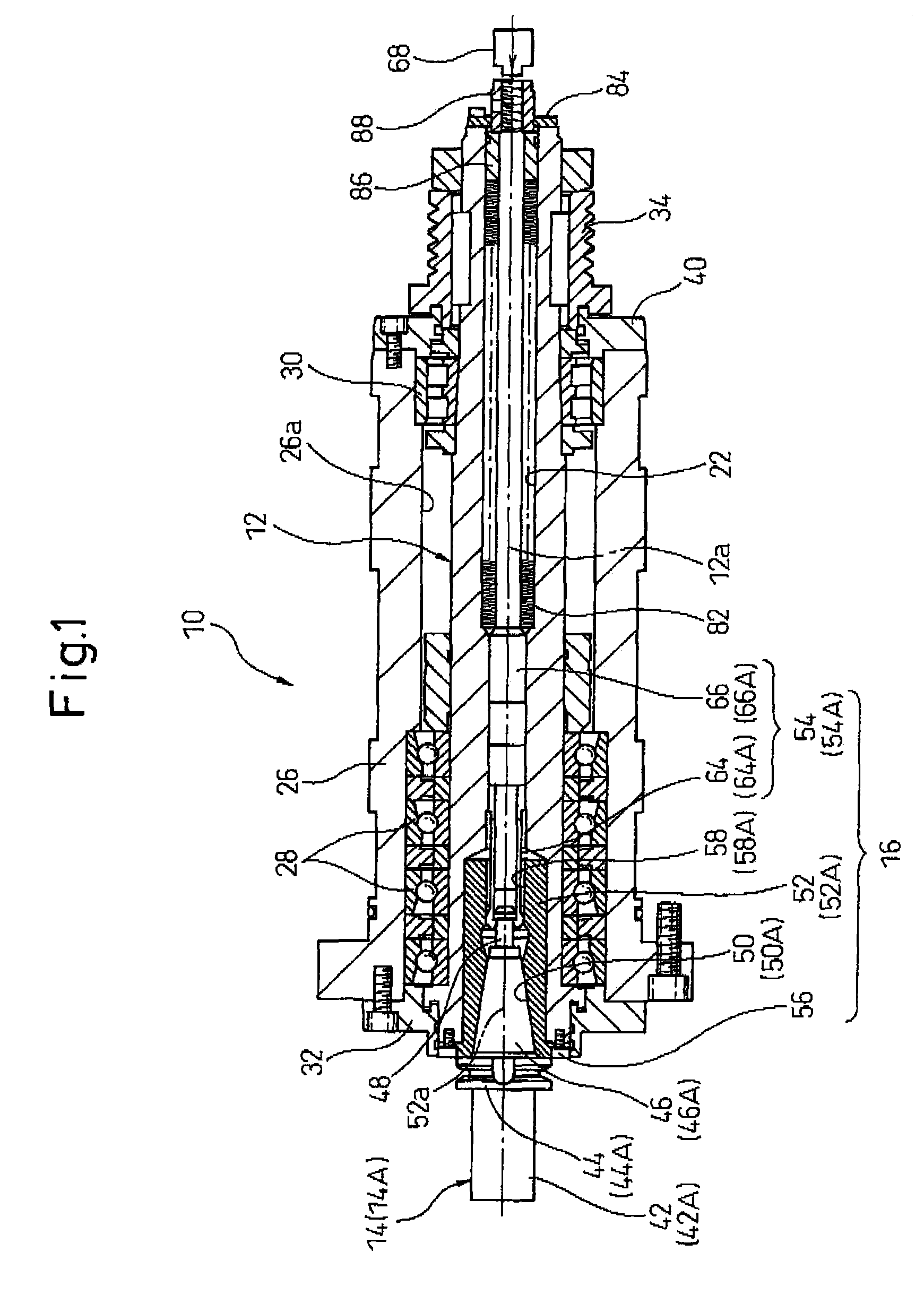
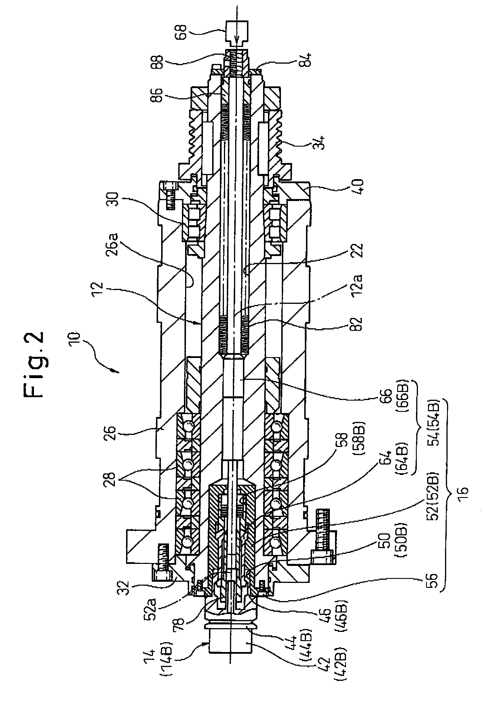
[0037]Referring to the drawings, FIGS. 1 and 2 are illustrations showing a spindle head device 10 according to the present invention, in respective states where different types of tool holders 14A, 14B (generally referred to as a tool holder 14) are retained on a common spindle 12; FIG. 3 is an illustration showing the spindle head device 10 in a state where a tool retaining mechanism 16 is detached from the spindle 12; FIG. 4 is an illustration showing a first unit 18 of the tool retaining mechanism 16 for retaining the first tool holder 14A on the spindle 12; and FIG. 5 is an illustration showing a second unit 20 of the tool retaining mechanism 16 for retaining the second tool holder 14B on the spindle 12. The spindle head device 10 is installed in a machine tool equipped with a spindle (so-called a tool spindle) fixedly supporting a tool and rotating, such as a milling machine, a machining center, etc.

[0038]As shown in FIGS. 1 and 2, the spindle head device 10 includes the spindl...

second embodiment

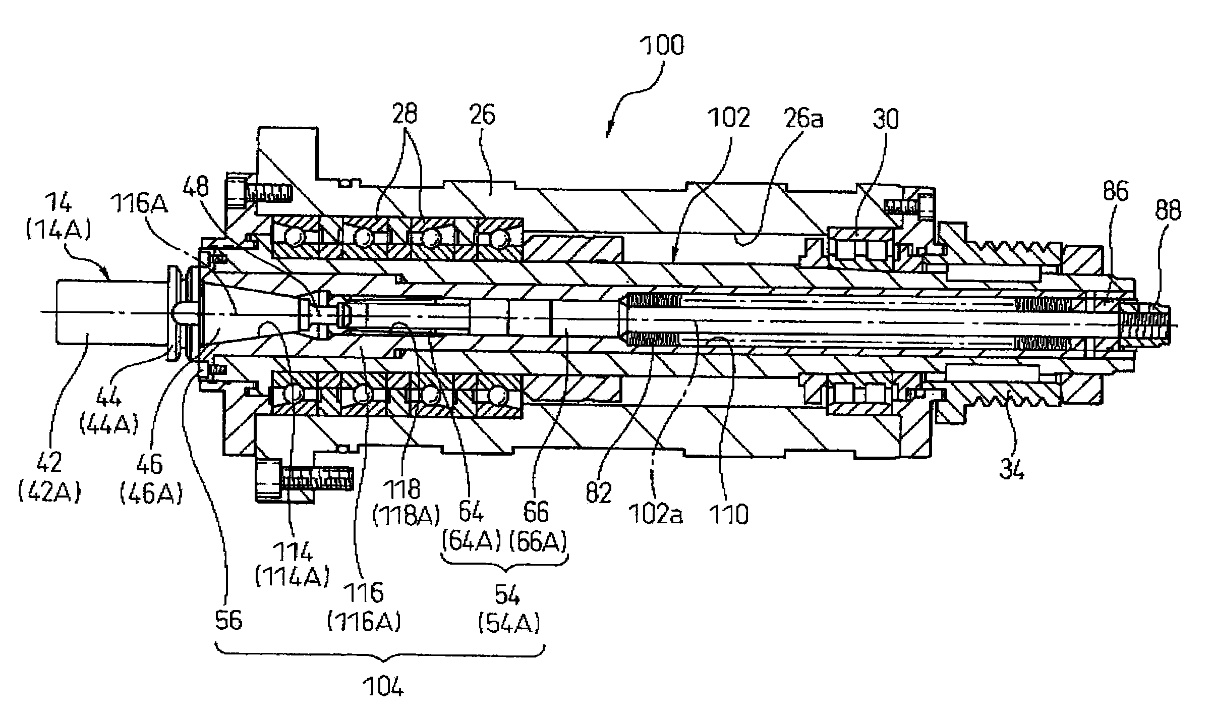
[0094]Similarly, as shown in FIGS. 14A and 14B, in the spindle head device 100 the spindle 102 may be provided, in a region adjacent to the axial front end (a left end, in the drawing) of the spindle-through-hole 110, with a fitting surface 132 having tapered shape with a diameter thereof increasing toward the front end opening. In this case, the tool support member 116A (FIG. 14A), 116B (FIG. 14B) is provided, in the axial front end region, with an outer surface 134 with a diameter thereof increasing in a tapering rate identical to the tapering rate of the fitting surface 132 toward the flange portion 120. In this configuration, when the tool support member 116 is contained in the spindle-through-hole 110 of the spindle 102, it is possible to easily make the center axes 102a, 116a coincide with each other, and thus to support the tool support member 116 on the spindle 102 in a centering manner.

[0095]FIG. 15 shows a machine tool 200 according to an embodiment of the present inventi...


PUM

PropertyMeasurementUnit
axial lengthaaaaaaaaaa
diameteraaaaaaaaaa
axial displacementaaaaaaaaaa

Abstract

A spindle head device (10) includes a spindle (12) and a tool retaining mechanism (16) detachably retaining a tool holder (14) on the spindle. The tool retaining mechanism includes a tool support member (52) having a receiving recess (50) detachably receiving the shank (46) of the tool holder, a tool clamp member (54) disposed to be displaceable with respect to the tool support member between an operative position and an inoperative position, and a mounting member (56) detachably mounting the tool support member and the tool clamp member to the spindle. The tool clamp member grips the shank of the tool holder and fixedly holds the shank to the receiving recess of the tool support member at an operative position, and, at an inoperative position, releases the shank to allow the tool holder to be attached or detached to or from the receiving recess.

Description

TECHNICAL FIELD[0001]The present invention relates to a spindle head device installed in a machine tool and including a tool spindle. The present invention also relates to a machine tool equipped with a spindle head device including a tool spindle.BACKGROUND ART[0002]A machine tool (e.g., a milling machine, a machining center, etc.) provided with a spindle (a, so-called tool spindle) for fixedly supporting a tool and rotating, is configured such that various cutting operations can be carried out by selecting a suitable tool from among several types of tools respectively fitted to tool holders and attaching it to an axial end of the spindle (hereinafter referred to as a spindle nose) in an exchangeable manner. To this end, generally, a machine tool is provided, inside a spindle head device including a tool spindle, with a tool retaining mechanism for detachably retaining respective tool holders on the spindle nose.[0003]A tool holder is provided with a chuck for chucking a tool, a sh...

Claims


Application Information

Patent Timeline
Patent Type & Authority Patents(United States)
IPC IPC(8): B23Q3/12
CPCB23B31/265B23B2260/034Y10T409/309464Y10T409/309352Y10T409/304032Y10T409/309408B23B31/117B23Q11/10
Inventor SHINANO, KEIZO
Owner CITIZEN WATCH CO LTD
Why Eureka
Try Eureka