High voltage mechanical splice connector

a technology of mechanical splicing and connectors, which is applied in the direction of positive displacement liquid engines, coupling device connections, piston pumps, etc., can solve the problems of connector components expanding, the current splicing media or materials used in the existing art may not be able to cope with the harsh environment in some wells, and may not be able to meet the harsh environment of some wells

Active Publication Date: 2013-02-26
BAKER HUGHES INC
View PDF13 Cites 13 Cited by
  • Summary
  • Abstract
  • Description
  • Claims
  • Application Information

AI Technical Summary

Benefits of technology

[0008]Embodiments of this application include devices that couple multi phase high voltage power cable to individual tube encapsulated, high voltage motor lead cables. The philosophy behind the device is that it can connect multi phase cable conductors multiple times, in a low profile manner that eliminates phase to phase shorts, along with providing multiple sealing barriers between the well annulus and connection.
[0009]The device can be manufactured in a controlled environment and factory acceptance tested before field installation, allowing for a superior field connection. The multi phase power cable will be prepped with individual connectors for each phase. Then a series of factory acceptance testing, both mechanical and electrical, will be performed to ensure integrity. Likewise, the tube encapsulate motor lead will be prepped with individual connectors. Then a series of factory acceptance testing, both mechanical and electrical will be performed to ensure integrity. Once the equipment has arrived in the field, both components can be connected quickly, elevating the use of a splice.
[0014]In alternative embodiments, an electrical power assembly for supplying power to a motor includes a motor lead having one end for connection to the motor and having a plurality of individual conductors, a power cable having one end for connection to a power source and having a plurality of individual conductors and a splice connector for joining each of the conductors of the motor lead to one of the conductors of the power cable. The splice connector may include a tubular metal fastener body with a motor lead end and a power cable end and fastener body threads on the power cable end and on the motor lead end of the fastener body. The splice connector may also include a metal nut assembly fixed to one of the power cable conductors having threads that engage the fastener body threads on the power cable end. An electrical contact on the conductor of the power cable and the conductor of the motor lead, may mate with each other in the interior of the fastener body. An elastomeric seal may be disposed between the nut assembly and the fastener body, the elastomeric seal including a plurality of expansion relief ports operable to collapse and relieve stresses exerted by the seal when the seal undergoes thermal expansion.

Problems solved by technology

In some wells, the well environment may be quite harsh with high temperatures and pressures and corrosive well fluids.
However, current splicing media or materials used in the existing art may not be capable of withstanding the harsh environments in some wells.
If these materials degrade, well fluids could enter the connection and a short could result that would require the pump assembly to be pulled and replaced.
In addition, the high temperature of the well will cause the components of the connector to expand.
This expansion may damage the connector and the connection by creating sufficient forces to the components of the splice connection to deform and damage them.
Conventional connection designs may be bulky and have large profiles.
However, there are some situations in which the target wells have size limitations that prevent the use of these conventional designs.

Method used


Image

  • High voltage mechanical splice connector
  • High voltage mechanical splice connector
  • High voltage mechanical splice connector

Examples


Embodiment Construction

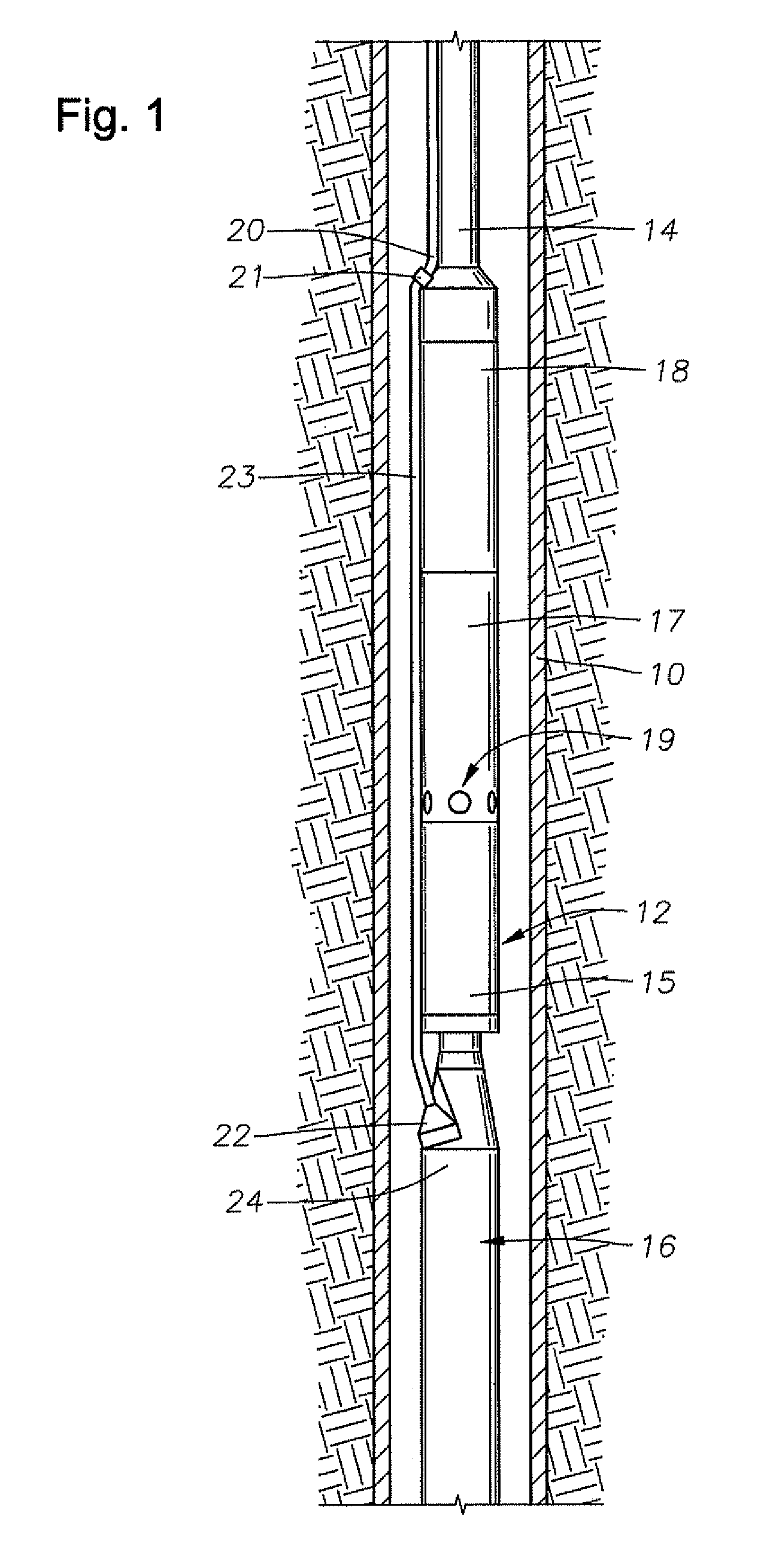
[0028]FIG. 1 is an elevational section view of cased well 10 having an ESP 12 disposed therein. ESP 12 includes an electric motor 16, a seal / equalizer section 15, an optional gas separator 17, and a pump 18. Pump 18 may comprise a centrifugal pump, a progressing cavity pump, or some other rotary pump. Fluid inlets 19 are shown provided on separator 17 for providing a passage for receiving fluid into pump 18. Production tubing 14 is coupled to pump 18 discharge for conveying pressurized production fluid from the ESP 12 to surface.

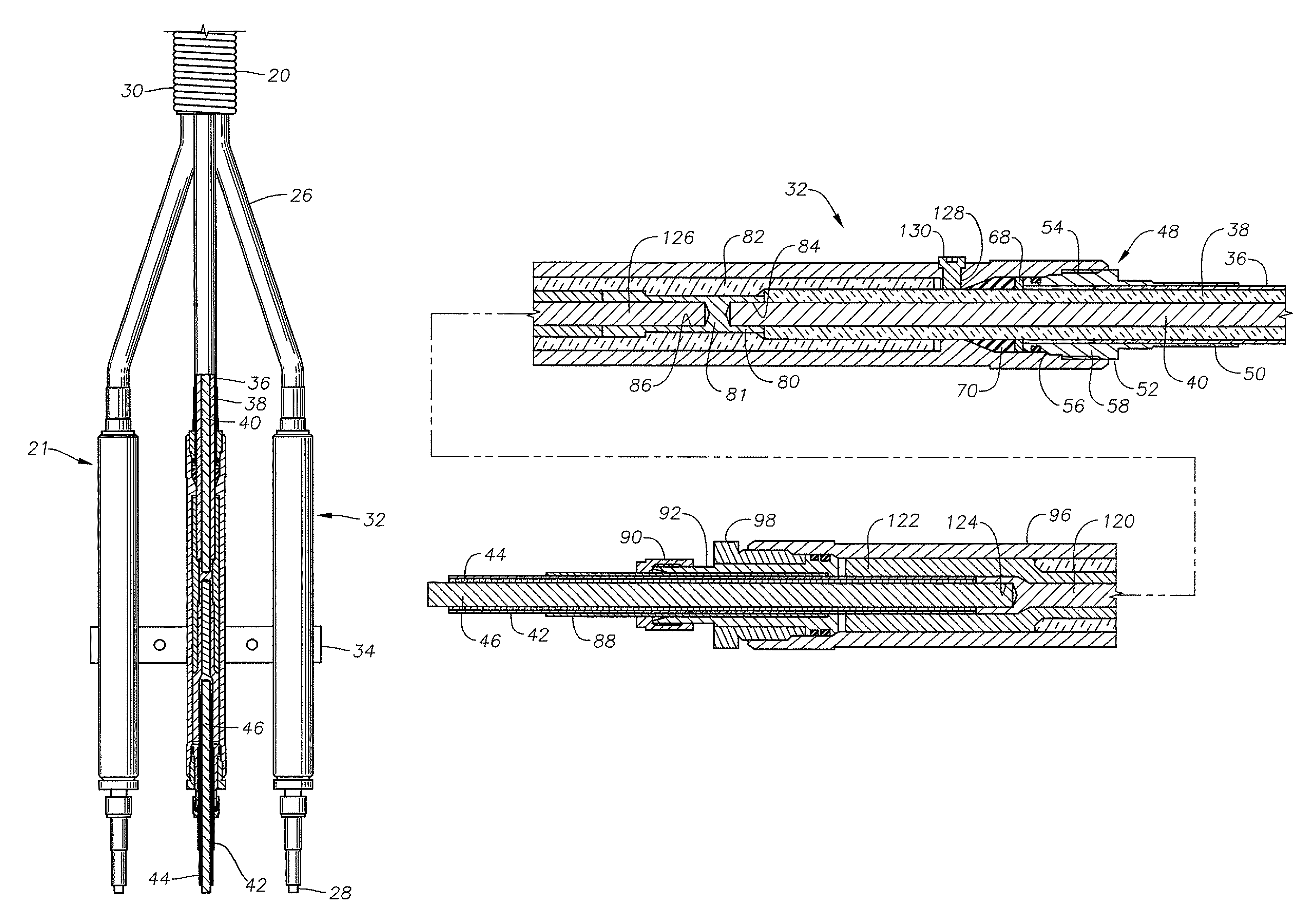
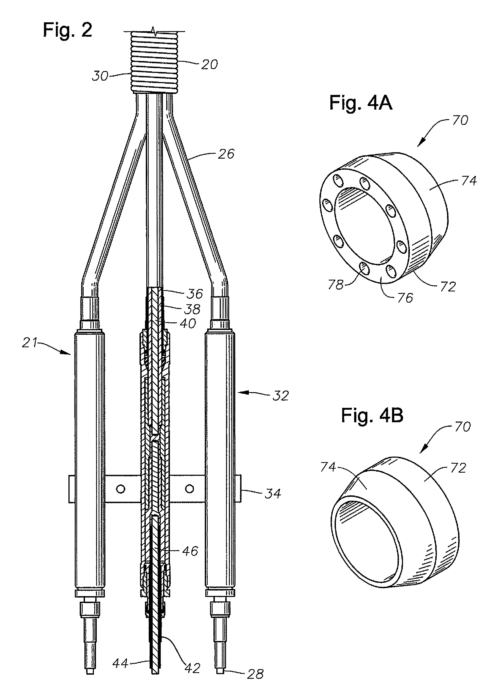
[0029]In this embodiment, power cable 20 extends alongside production tubing 14, terminating in a splice or connector 21 that electrically couples cable 20 to a second power cable, or motor lead 23. Power cable 20 may be a high voltage, multi phase power cable, such as a three phase power cable. On the lower end of power cable 20, motor lead 23 connects to a pothead connector 22 that electrically connects and secures motor lead 23 to motor housing 24 of elec...


PUM


Abstract

An electrical power assembly comprises a motor lead with individual metal sheathed conductors, a power cable with individual metal sheathed conductors and a splice connector for connecting each of the conductors. Each splice connector has a tubular metal fastener body with an upward facing shoulder at an upper end and a downward facing shoulder at a lower end. A metal nut assembly is fixed to one of the power cable conductors with a downward facing shoulder in metal-to-metal sealing engagement with the upward facing shoulder of the fastener body. A metal coupler fixed to one of the motor lead conductors with an upward facing shoulder in metal-to-metal sealing engagement with the downward facing shoulder of the fastener body. Contacts electrically connect one of the motor lead conductors to one of the power cable conductors within the fastener body. An elastomeric seal disposed between the nut assembly and the fastener body, has expansion relief voids operable to collapse and relieve stresses exerted by the seal when the seal undergoes thermal expansion.

Description

FIELD OF THE INVENTION[0001]This invention relates in general to electrical submersible pump assemblies for subterranean well production, in particular, to a connector for connecting a power cable to a motor lead of the pump assembly.BACKGROUND OF THE INVENTION[0002]Submersible pumping systems are often used in hydrocarbon producing wells for pumping fluids from within the well bore to the surface. These fluids are generally liquids and include produced liquid hydrocarbon as well as water. One type of system used in this application employs a electrical submersible pumping system (ESP). A common type of ESP comprises a centrifugal pump suspended on a string of tubing within a casing of the well. The pump is driven by a downhole electrical motor, normally a three-phase AC type. A power line extends from a power source at the surface alongside the tubing to the motor to supply power.[0003]Typically the power line is made up of two sections, a motor lead and a power cable. The motor le...

Claims


Application Information

Patent Timeline
Patent Type & Authority Patents(United States)
IPC IPC(8): H01R13/58
CPCH01R13/5205H01R2201/10H01R13/58H02G15/18
Inventor FREY, JEFFREY G.LINGENFELTER, DONALD RAYGLASSCOCK, TERRY L.TETZLAFF, STEVEN K.CRAIG, CHAD A.
Owner BAKER HUGHES INC
Why Eureka
Try Eureka