Cooling of electrical components

a technology for electrical components and cooling media, applied in the direction of electrical apparatus construction details, indirect heat exchangers, lighting and heating apparatus, etc., can solve the problems of large amount of cooling media, large amount of cooling medium, and large amount of heat generation, and achieve good cooling, energy saving, and sufficient cooling

Active Publication Date: 2013-02-26
HITACHI ENERGY SWITZERLAND AG
View PDF13 Cites 10 Cited by
  • Summary
  • Abstract
  • Description
  • Claims
  • Application Information

AI Technical Summary

Benefits of technology

[0017]The present invention has a number of advantages. Through cooling the first group before the second group using the same cooling medium less cooling medium is used compared with parallel cooling. Since the electrical components in the first group are cooled first, the cooling of these electrical components in the first group is efficient. However, also the cooling of the electrical components in the second group may be efficient enough even though they receive cooling medium that has already been used for cooling the first group. The reason for this is that the electrical components of the second group may not necessarily have the same losses as the components in the first group. This means that good cooling may be obtained despite them being provided last in the cooling chain. This has the further advantage of the cooling medium not having to be provided at the same temperature that is required for the first group. The invention therefore provides energy saving in that less cooling medium may be used in cooling and the same cooling medium can be used for cooling both groups while still obtaining sufficient cooling. Another advantage is that the number of ducts and joints are reduced.

Problems solved by technology

Due to these large currents, the components can generate large amounts of heat and therefore they need cooling.
One problem with this approach is that a large amount of cooling medium may be used.

Method used


Image

  • Cooling of electrical components
  • Cooling of electrical components
  • Cooling of electrical components

Examples


first embodiment

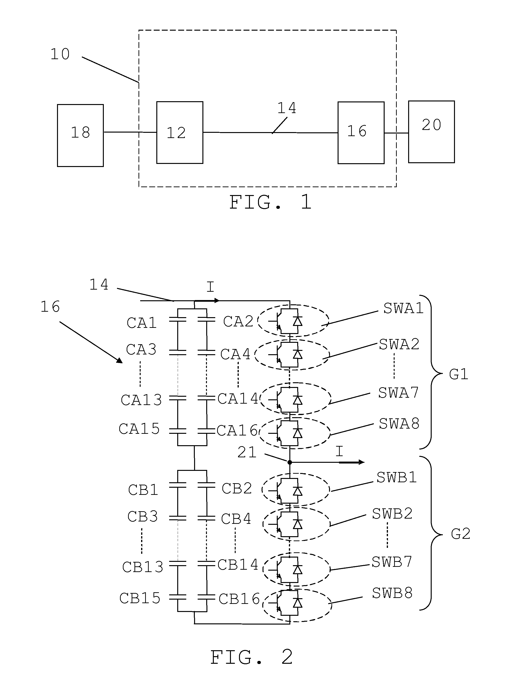
[0029]Both the converters 12 and 16 may be any type of converters, such as line-commutated Current Source Converters (CSC) or forced commutated Voltage Source Converters (VSC). In the first embodiment that is being described here they are both VSCs.

[0030]FIG. 2 shows an electrical circuit diagram of a part of the second converter 16. This converter is merely used to exemplify the present invention.

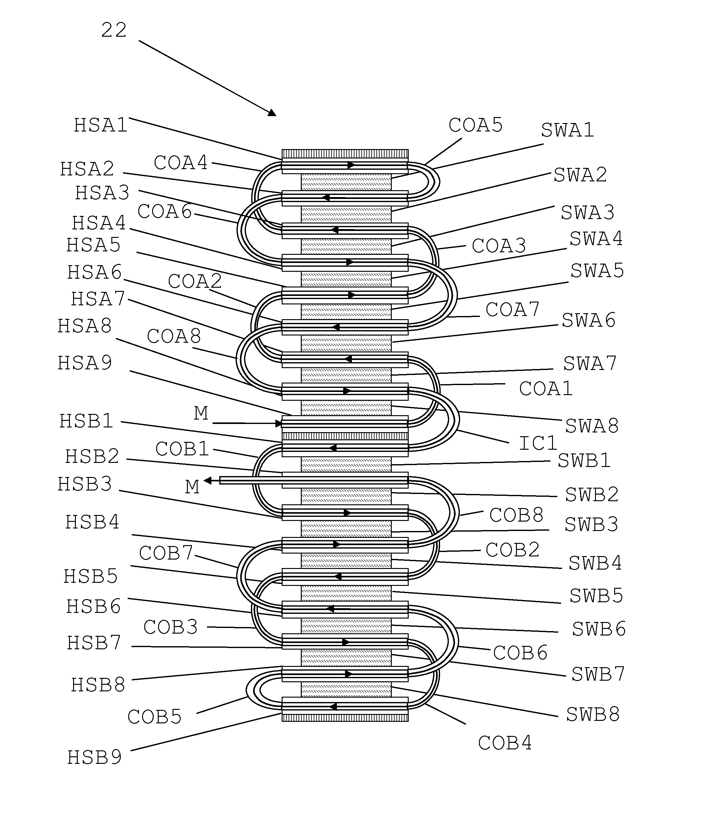
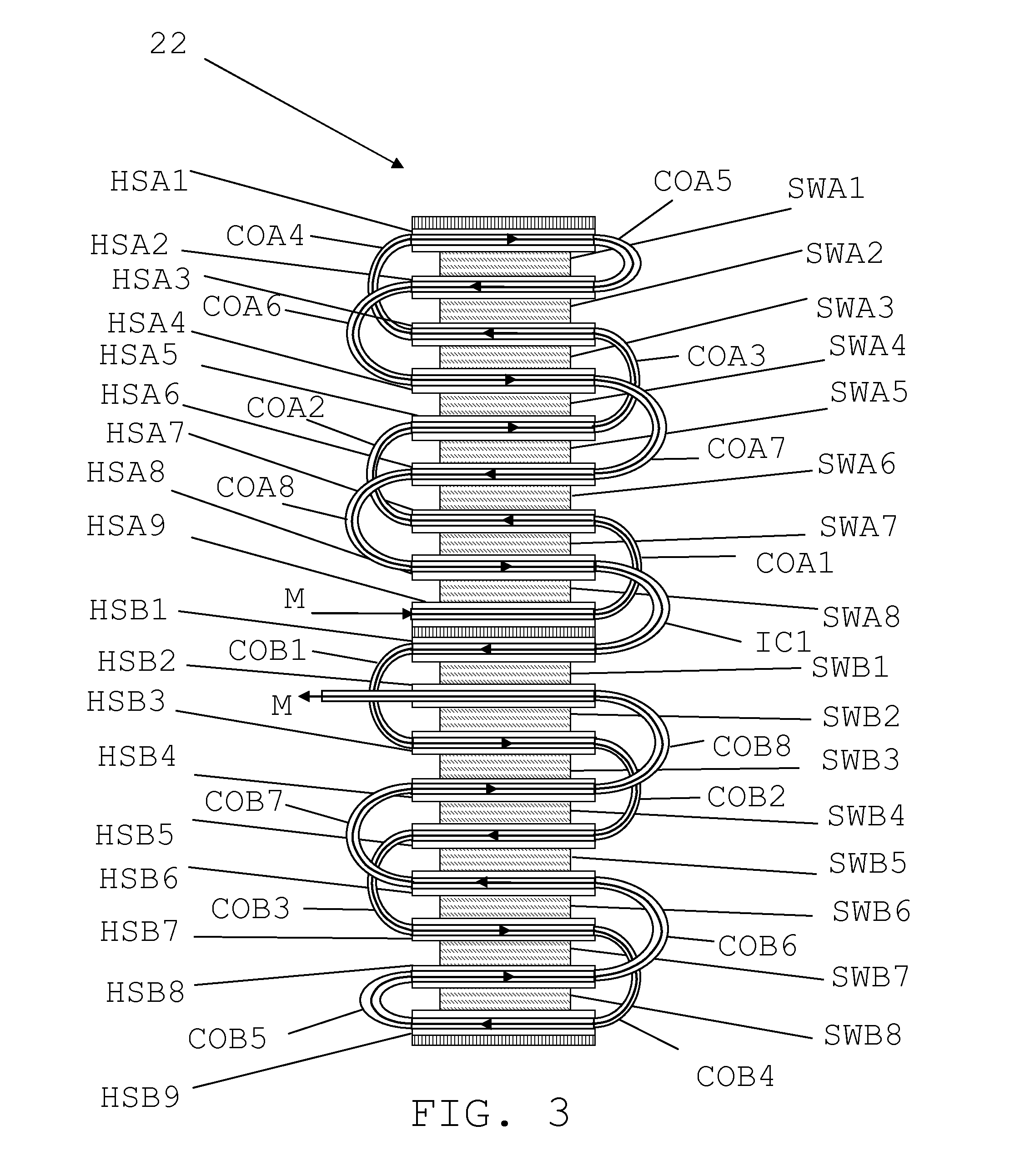
[0031]In FIG. 2 there is a first and a second group G1 and G2 of electrical components, in the form of switching elements. The switching elements are according to a first embodiment of the invention IGBTs, each provided as a transistor with anti-parallel diode. There are here eight components SWA1, SWA2, . . . SWA7 and SWA8 in the first group G1, where only the first two and the last two are shown, and eight components SWB1, SWB2, . . . SWB7 and SWB8 in the second group G2, where only the first two and the last two are shown. The components in the first group G1 are connected in series wit...

second embodiment

[0091]It should here be realized that the second embodiment may be varied in that it is possible to add more groups in a similar manner, which groups are provided with transporting arrangements for cooling in the same way.

third embodiment

[0092]FIG. 8 shows a cooling arrangement for cells CCA1, CCA2, CCA3, CCA4, CCA5 and CCA6 of the type described in relation to FIG. 5 being connected in cascade. There are here three cells CCA1, CCA2 and CCA3 in an upper converter arm and three cells CCA4, CCA5 and CCA6 in a lower converter arm. Each of these cells is provided with a corresponding transporting arrangement TAa, TAb, TAc, Tad, TAe and TAf, connected such that the cells in the upper arm are cooled before the cells in the lower arm.

[0093]The current valve elements used in the cells have been described as employing IGBTs. It should be realized that other types of current valve elements may be used, such as elements based on thyristors, MOSFET transistors, GTOs (Gate Turn-Off Thyristor), IGCTs (Integrated Gate Commuted Thyristor) and mercury arc valves.


PUM


Abstract

The invention concerns a converter as well as a cooling device and a method for cooling at least a first and a second group of electrically interconnected electrical components (SWA1, SWA2, SWA3, SWA4, SWA5, SWA6, SWA7, SWA8, SWB1, SWB2, SWB3, SWB4, SWB5, SWB6, SWB7, SWB8) in the converter, where the first and second groups are placed on opposite sides of a conductor leading to a connection terminal of the converter. The cooling device (22) comprises a first transporting arrangement (HSA1, HSA2, HSA3, HSA4, HSA5, HSA6, HSA7, HSA8, HSA9, COA1, COA2, COA3, COA4, COA5, COA6, COA7, COA8) transporting cooling medium (M) past the first group and a second transporting arrangement (HSB1, HSB2, HSB3, HSB4, HSB5, HSB6, HSB7, HSB8, HSB9, COB1, COB2, COB3, COB4, COB5, COB6, COB7, COB8) transporting the same cooling medium past the second group.

Description

FIELD OF INVENTION[0001]The present invention generally relates to cooling of electrical components. More particularly the present invention relates to a cooling device and method for cooling at least a first and a second group of electrically interconnected electrical components as well as a converter including such a cooling device.BACKGROUND[0002]In power transmission systems and then especially in High Voltage Direct Current (HVDC) power transmission systems, the current running through electrical components can be very high. Typical such components are current valve components like thyristors and Insulated Gate Bipolar Transistors (IGBTs). Due to these large currents, the components can generate large amounts of heat and therefore they need cooling. The way that they are cooled is therefore very important.[0003]One cooling device in this field is described in WO 2007 / 149023. Here groups of electrical components to be cooled are placed in rows in a column in contact with cooling...

Claims


Application Information

Patent Timeline
Patent Type & Authority Patents(United States)
IPC IPC(8): H05K7/20
CPCH01L23/473H01L25/117H02M7/003H01L2924/13055H01L2924/13091H01L2924/19041H01L2924/0002H02M2007/4835H01L2924/00H02M7/4835H01L23/34
Inventor JACOBSON, BJORNHEDBLAD, PER-OLOF
Owner HITACHI ENERGY SWITZERLAND AG
Why Eureka
Try Eureka