
Monitor chaining and docking mechanism

a technology of monitors and docking devices, applied in the field of computer systems, can solve the problems of cpu burden, complicated system operation and maintenance, and usb based solutions, and achieve the effect of significant reducing the overhead of the cpu

Active Publication Date: 2013-03-12
SMSC HLDG
View PDF11 Cites 22 Cited by
  • Summary
  • Abstract
  • Description
  • Claims
  • Application Information

AI Technical Summary

Benefits of technology

The patent is about a circuit that supports digital content protection for a display port. The circuit can handle multiple data lanes and an auxiliary channel, which reduces processing demands on the host computer. The circuit can also be used with a graphics card or other host computer component that has multiple display port interfaces. The built-in harmonized content protection (HDCP) for display port allows for secure content playback. Additionally, the circuit can provide exposed serial ports for users to access the host computer independently.

Problems solved by technology

Modern computer systems often include multiple monitors and other peripheral devices with corresponding communication requirements which may lead to a proliferation of cables that clutter the workspace and may complicate operation and maintenance of the system.
However, USB based solutions entail a heavy CPU burden, and complex proprietary software generally must be developed and maintained across operating systems.
Moreover, content protection is currently not supported.
Gigabit Ethernet does not have sufficient bandwidth to support uncompressed video, and 10 Gigabit Ethernet is not currently cost effective.
Additionally, compressed video may introduce visual artifacts when video is being displayed to the end user.
Wireless technologies currently are also not suitable due to low bandwidth.

Method used


Image

  • Monitor chaining and docking mechanism
  • Monitor chaining and docking mechanism
  • Monitor chaining and docking mechanism

Examples


Embodiment Construction

Terms

[0024]The following is a glossary of terms used in the present application:

[0025]Memory Medium—Any of various types of memory devices or storage devices. The term “memory medium” is intended to include an installation medium, e.g., a CD-ROM, floppy disks 104, or tape device; a computer system memory or random access memory such as DRAM, DDR RAM, SRAM, EDO RAM, Rambus RAM, etc.; a non-volatile memory such as a Flash, magnetic media, e.g., a hard drive, or optical storage; registers, or other similar types of memory elements, etc. The memory medium may comprise other types of memory as well or combinations thereof. In addition, the memory medium may be located in a first computer in which the programs are executed, or may be located in a second different computer which connects to the first computer over a network, such as the Internet. In the latter instance, the second computer may provide program instructions to the first computer for execution. The term “memory medium” may in...


PUM


Abstract

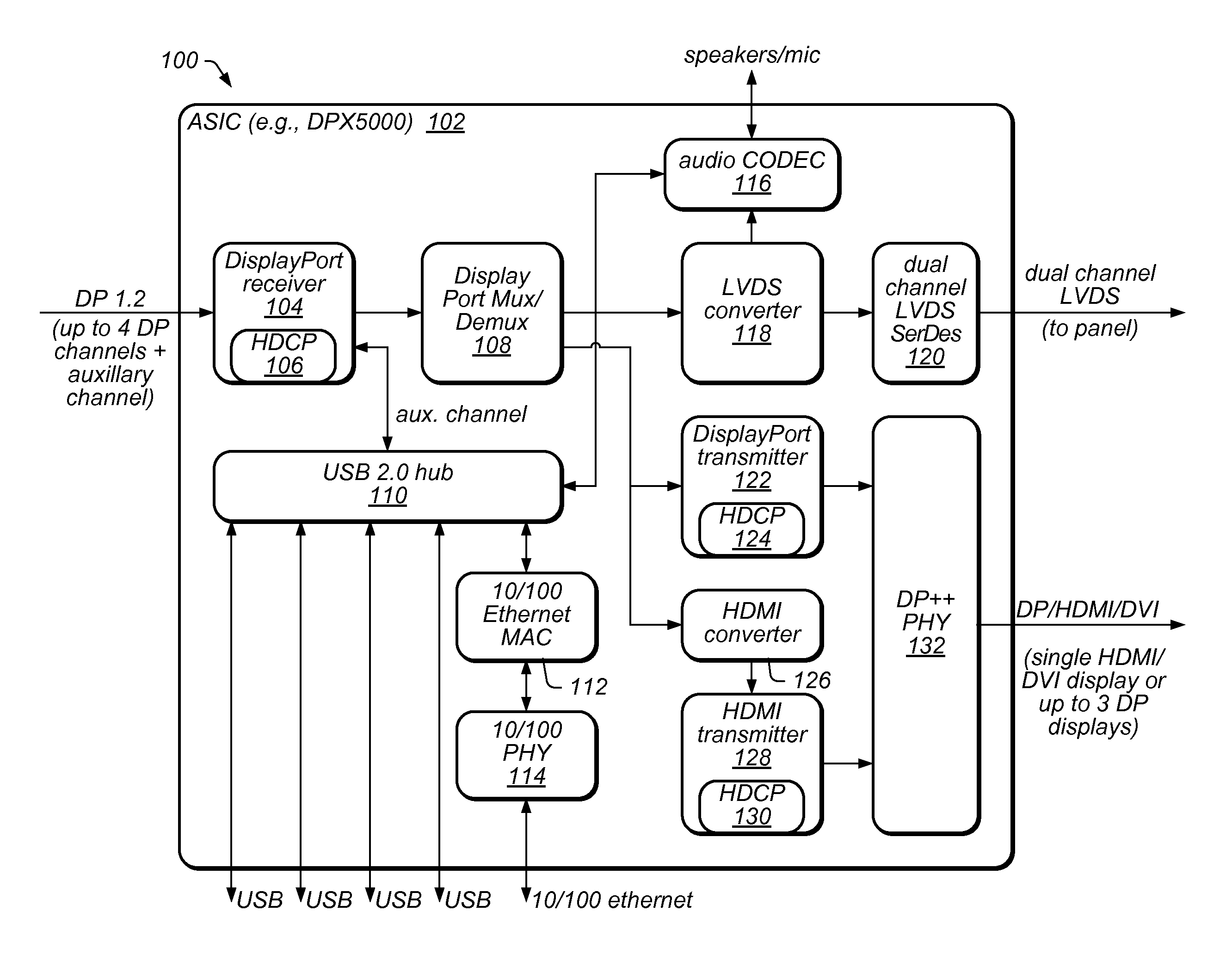
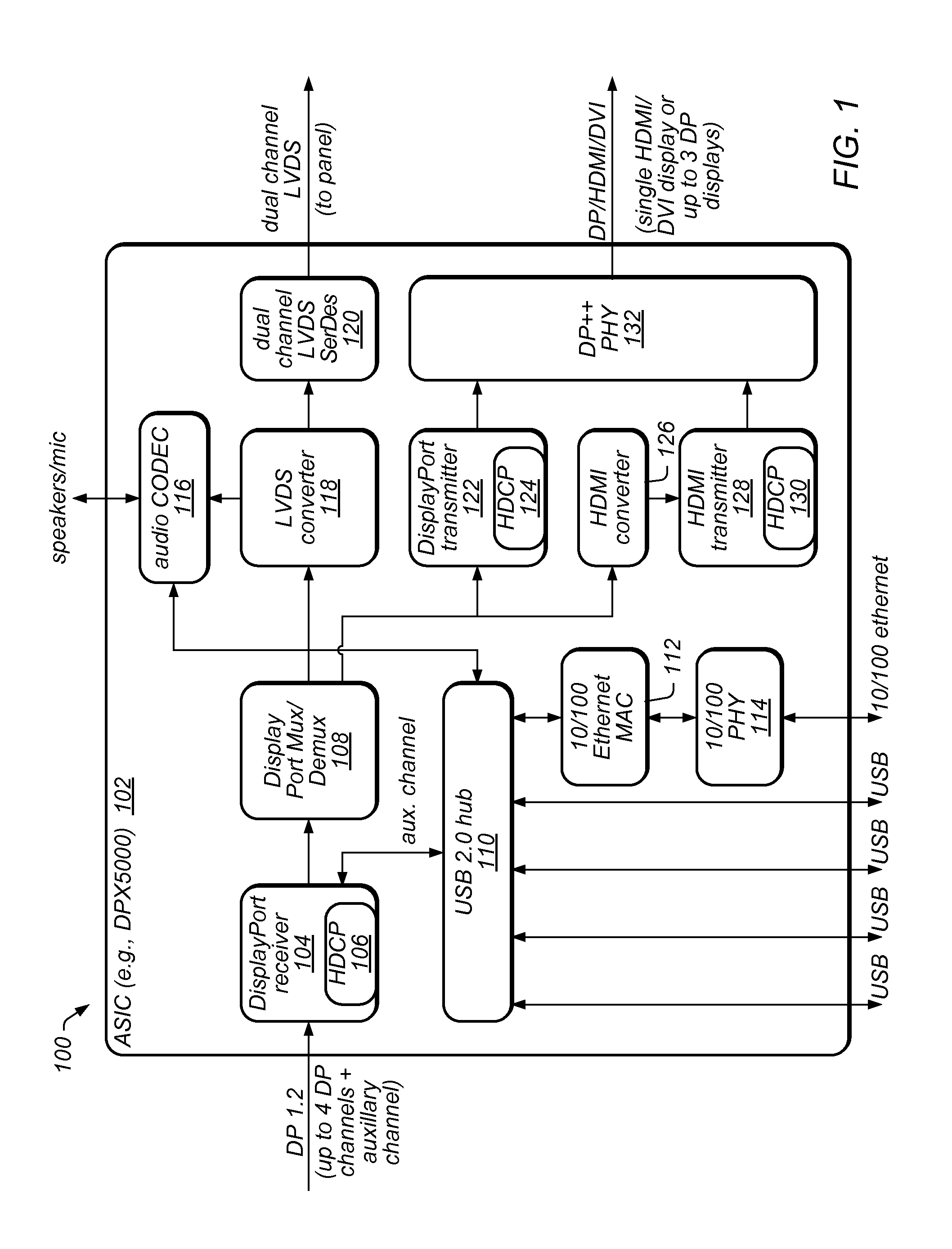
A circuit that supports multiple monitors, docking functions, and protected content via one cable. The circuit includes a receiver that receives multiple video streams, each including respective video data, a mux / demux, coupled to the receiver, that determines which video stream to display on a monitor, a low-voltage differential signaling (LVDS) converter, coupled to the mux / demux, that generates an LVDS signal based on the video data of the determined video stream, an LVDS serializer / deserializer, coupled to the LVDS converter, that generates a signal based on the LVDS signal and sends the signal to a display panel of the monitor for display, a transmitter coupled to the mux / demux, and a transmit physical interface (TPI) coupled to the transmitter. The mux / demux sends at least a remainder of the video streams to the transmitter, which sends them to the TPI, which transmits them as output, useable as input to further instances of the circuit.

Description

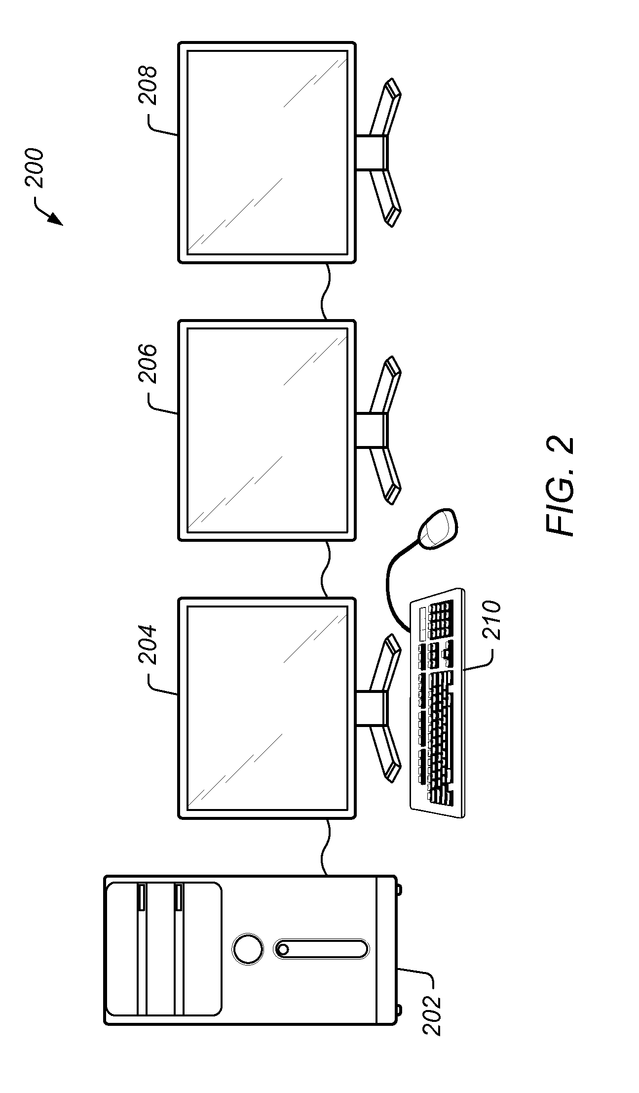
CONTINUATION DATA[0001]This application claims benefit of priority to U.S. Provisional Application 61 / 381,698, titled “Display Port Docking Mechanism”, which was filed Sep. 10, 2010, whose inventors are John F. Sisto and Charles Forni, and which is hereby incorporated by reference in its entirety as though fully and completely set forth herein.BACKGROUND OF THE INVENTION[0002]1. Field of the Invention[0003]This invention is related to computer systems, and more particularly, to a mechanism that supports multiple monitors, docking functions, and protected content via a single cable.[0004]2. Description of the Related Art[0005]Modern computer systems often include multiple monitors and other peripheral devices with corresponding communication requirements which may lead to a proliferation of cables that clutter the workspace and may complicate operation and maintenance of the system. Universal Serial Bus (USB) is currently a popular technology that allows both video and other function...

Claims


Application Information

Patent Timeline
Patent Type & Authority Patents(United States)
IPC IPC(8): G09G5/00
CPCG09G5/006H04N9/67G06F3/1431G09G2370/042G09G2370/10G09G2370/12G09G2370/14G09G2370/047
Inventor SISTO, JOHN F.FORNI, CHARLES A.
Owner SMSC HLDG
Learn More