Magnetic resonance thermometry method

a magnetic resonance and thermometry technology, applied in the field of high intensity focused ultrasound (hifu), can solve the problems of increasing the the overall treatment time, difficult in practical applications to monitor the temperature changes outside the focus point, etc., and achieves the reduction of temperature errors and complexity of the temperature measurement. , the effect of improving the speed of the whole treatment process

Active Publication Date: 2013-03-19
SIEMENS HEALTHCARE GMBH
View PDF3 Cites 5 Cited by
  • Summary
  • Abstract
  • Description
  • Claims
  • Application Information

AI Technical Summary

Benefits of technology

[0008]An object of the present invention is to provide a method for reducing errors in the measurement of temperature by a magnetic resonance imaging method, for use in obtaining accurate temperature change in a heated area.
[0009]The present invention provides a method for reducing errors in the measurement of temperature by a magnetic resonance imaging method, for use in MRI guided HIFU equipment, that includes acquiring an MR phase image, as a reference image, before heating an area to be heated with the HIFU equipment; acquiring another MR phase image, as a heated image, during or after the heating by the HIFU equipment, and calculating the temperature change in the heated area according to the heated image and the reference image, and automatically compensating the temperature change according to a change in the magnetic field caused by a position change of an ultrasonic transducer in said HIFU equipment.
[0017]From the abovementioned solutions it can be seen that since the present invention compensates the temperature measurement according to the magnetic field caused by the ultrasonic transducer, it can reduce significantly the temperature errors resulting from the position changes of the ultrasonic transducer. In comparison with the existing single reference image method, the present invention does not need to acquire a large number of reference images for different positions of the ultrasonic transducer, so the complexity of the temperature measurement is reduced and the speed of the whole treatment process is increased. In comparison with the existing self-reference method, the present invention can accurately obtain the temperature changes in the heated area, thus providing stable results of temperature measurement.

Problems solved by technology

During a practical heating process, however, after the reference image is acquired changes may occur in the position of the ultrasonic transducer (i.e. the treatment head), and the susceptibility change resulting from the movements of the ultrasonic transducer causes changes in the static magnetic field of the focal region of the ultrasonic transducer, so that the subtraction of the heated image and the reference image produces an additional phase difference, thus causing errors in the temperature measurement.
However, since the spatial range used by a reference image is very small, while the ultrasonic transducer moves within a relatively large spatial range in the HIFU treatment process, it is necessary to acquire reference images frequently for various positions in order to measure the temperature of each focal position of the ultrasonic transducer, and this increases the complexity of the temperature measurement and the overall treatment time.
The temperature change monitored using this method is limited to the vicinity of the focus of HIFU, and it is very difficult in practical applications to monitor the temperature changes outside the focus point.
Furthermore, the accuracy of the polynomial fitting and extrapolation and the complexity of the phase image are dependent on the size of the heated area, and it is relatively difficult to obtain stable, consistent and accurate results in general.

Method used


Image

  • Magnetic resonance thermometry method
  • Magnetic resonance thermometry method
  • Magnetic resonance thermometry method

Examples


Embodiment Construction

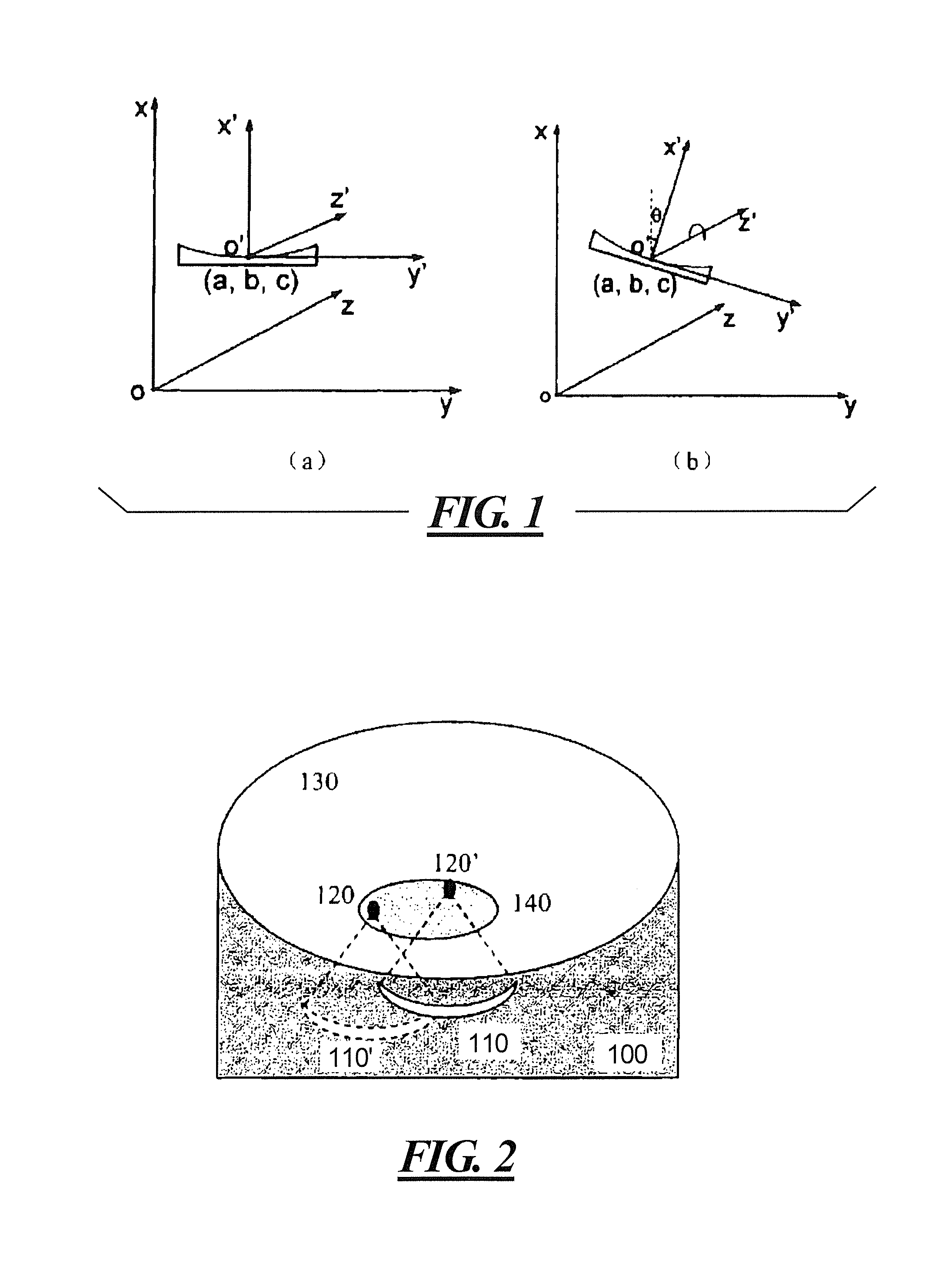
[0021]FIG. 1 is a schematic diagram of a coordinate system of the ultrasonic transducer and a coordinate system of the magnet in an embodiment of the present invention, in which the coordinate system xyz represents the coordinate system of the magnetic body, and the coordinate system x′ y′ z′ represents the coordinate system of the ultrasonic transducer, wherein (a) represents that the ultrasonic transducer is located at the original position, and (b) represents the position of the ultrasonic transducer after having been rotated about the direction of the magnetic field B0.

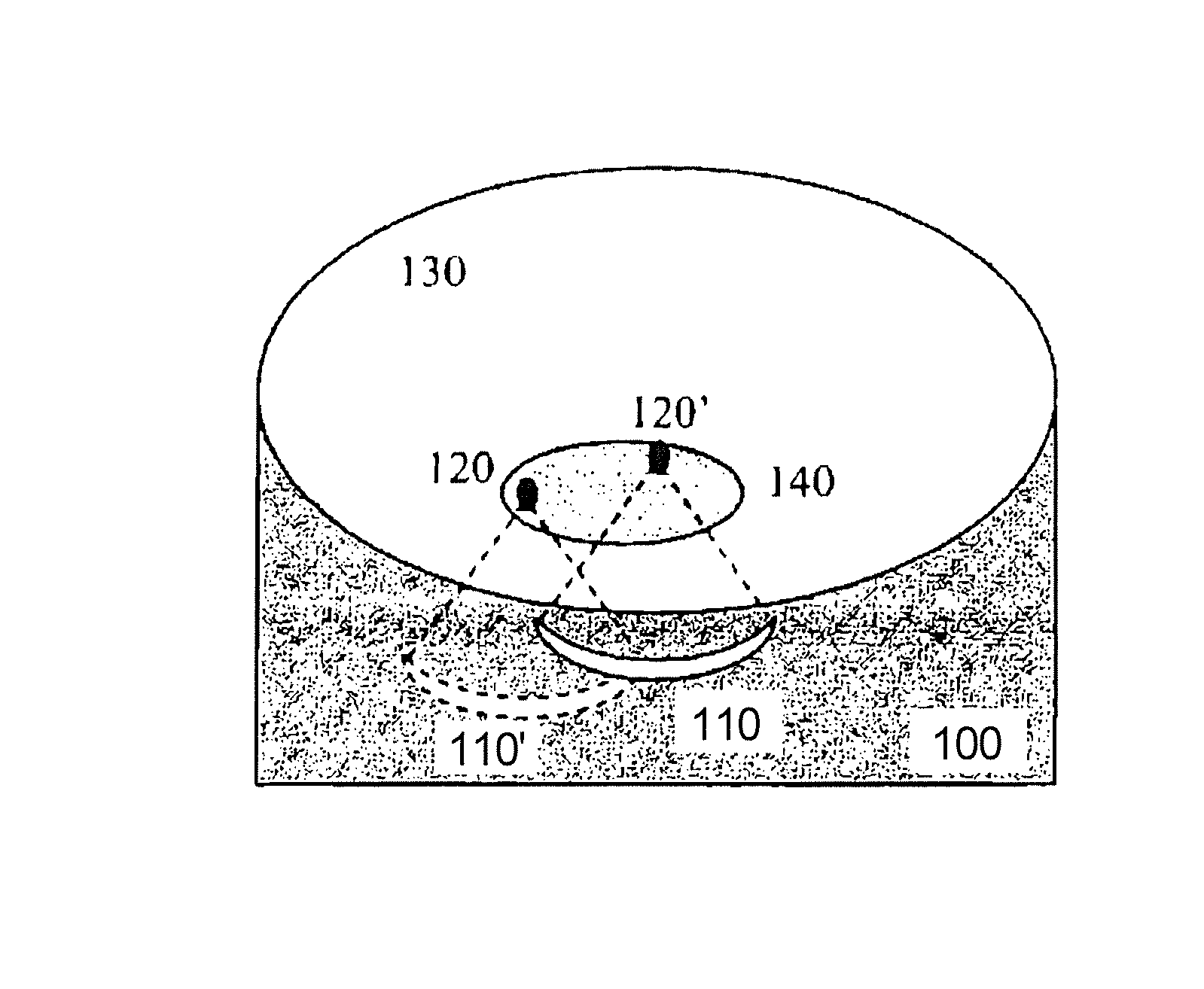
[0022]FIG. 2 is a schematic diagram of the movement of the position of the ultrasonic transducer in the embodiment of the present invention, in which 100 represents a water tank, 110 and 110′ respectively represent the ultrasonic transducer before and after being moved, 120 and 120′ respectively represent the focus points corresponding to 110 and 110′, 130 represents the body of a patient, and 140 represents the a...


PUM


Abstract

A method for reducing errors in the measurement of temperature by magnetic resonance, for use in magnetic resonance imaging-guided HIFU equipment, includes acquiring an MR phase image, as a reference image, before heating an area to be heated with the HIFU equipment; acquiring another MR phase image, as a heated image, during or after the heating by the HIFU equipment; and calculating the temperature change in the heated area according to said heated image and said reference image; and making compensation to said temperature change according to the change in the magnetic field caused by the position change of an ultrasonic transducer in said HIFU equipment. The method can reduce significantly the temperature errors resulting from the position changes of the ultrasonic transducer.

Description

BACKGROUND OF THE INVENTION[0001]1. Field of the Invention[0002]The present invention relates to the field of high intensity focused ultrasound (HIFU) monitored by magnetic resonance imaging (MRI) and, particularly, to a method for reducing errors in the measurement of temperature of MRI guided HIFU equipment.[0003]2. Description of the Prior Art[0004]Magnetic resonance (MR) thermometry based on proton resonance frequency (PRF) shift can be used to monitor temperature changes in an area heated by HIFU in MRI-guided HIFU equipment, based on the phenomenon of the resonance frequency of the protons in water being offset (shifted) dependent on the temperature change. MR thermometry based on PRF-shift requires that a base image (MR phase image) before heating, also referred to as a reference image, be generated, with the reference image providing information on a reference phase. By subtraction from the phase image (also referred to as a heated image) acquired during heating or after hea...

Claims


Application Information

Patent Timeline
Patent Type & Authority Patents(United States)
IPC IPC(8): A61B5/05
CPCA61N7/02G01K7/36G01R33/4804G01R33/4814A61B2017/00084A61B2019/5236G01K2213/00A61B2090/374
Inventor ZHOU, XIAO DONGNI, CHENG
Owner SIEMENS HEALTHCARE GMBH
Why Eureka
Try Eureka