
Spread spectrum clock generating circuit

a technology of spread spectrum clock and generating circuit, which is applied in the field ofic, can solve the problems of increasing increasing the frequency change of finally obtained spread spectrum clock, and high accuracy of interpolation circuits, so as to reduce the area and power consumption of circuits and improve reliability.

Inactive Publication Date: 2013-03-26
IPGOAL MICROELECTRONICS (SICHUAN) CO LTD
View PDF2 Cites 0 Cited by
  • Summary
  • Abstract
  • Description
  • Claims
  • Application Information

AI Technical Summary

Benefits of technology

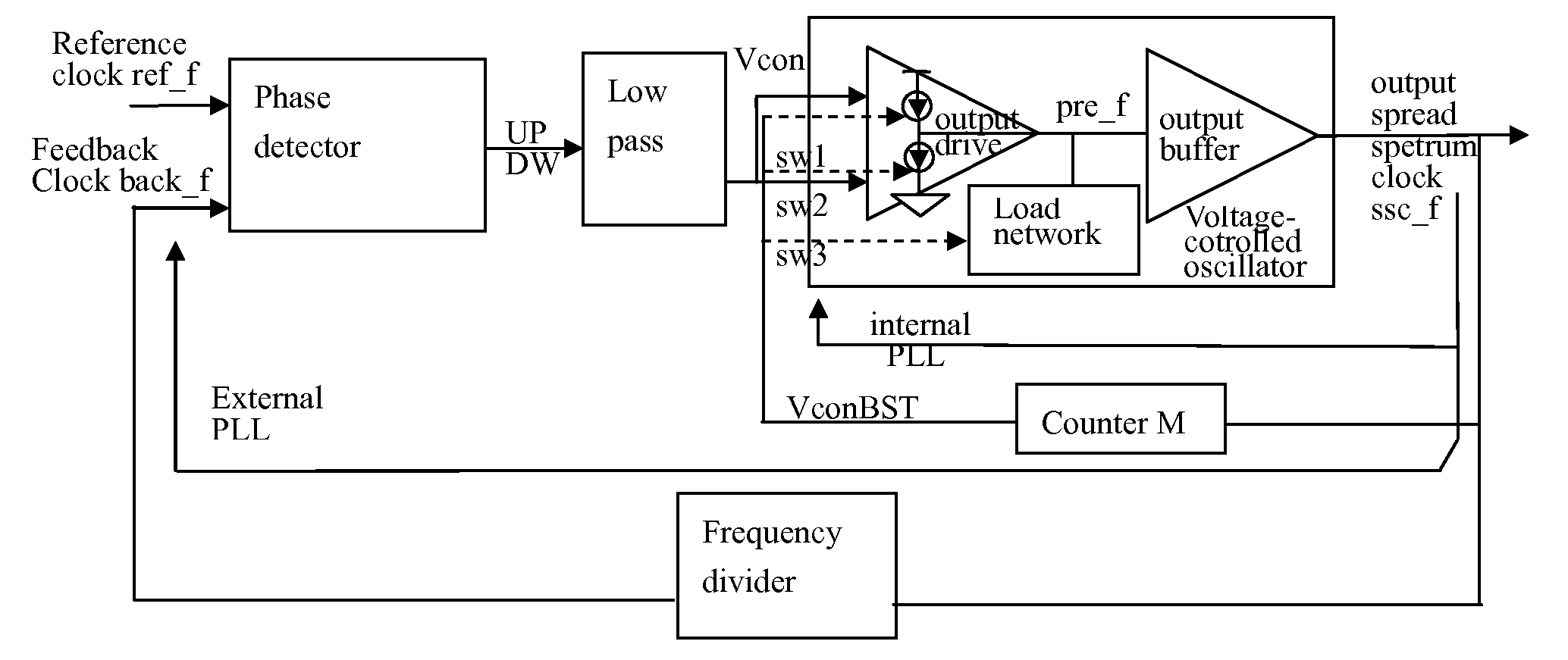
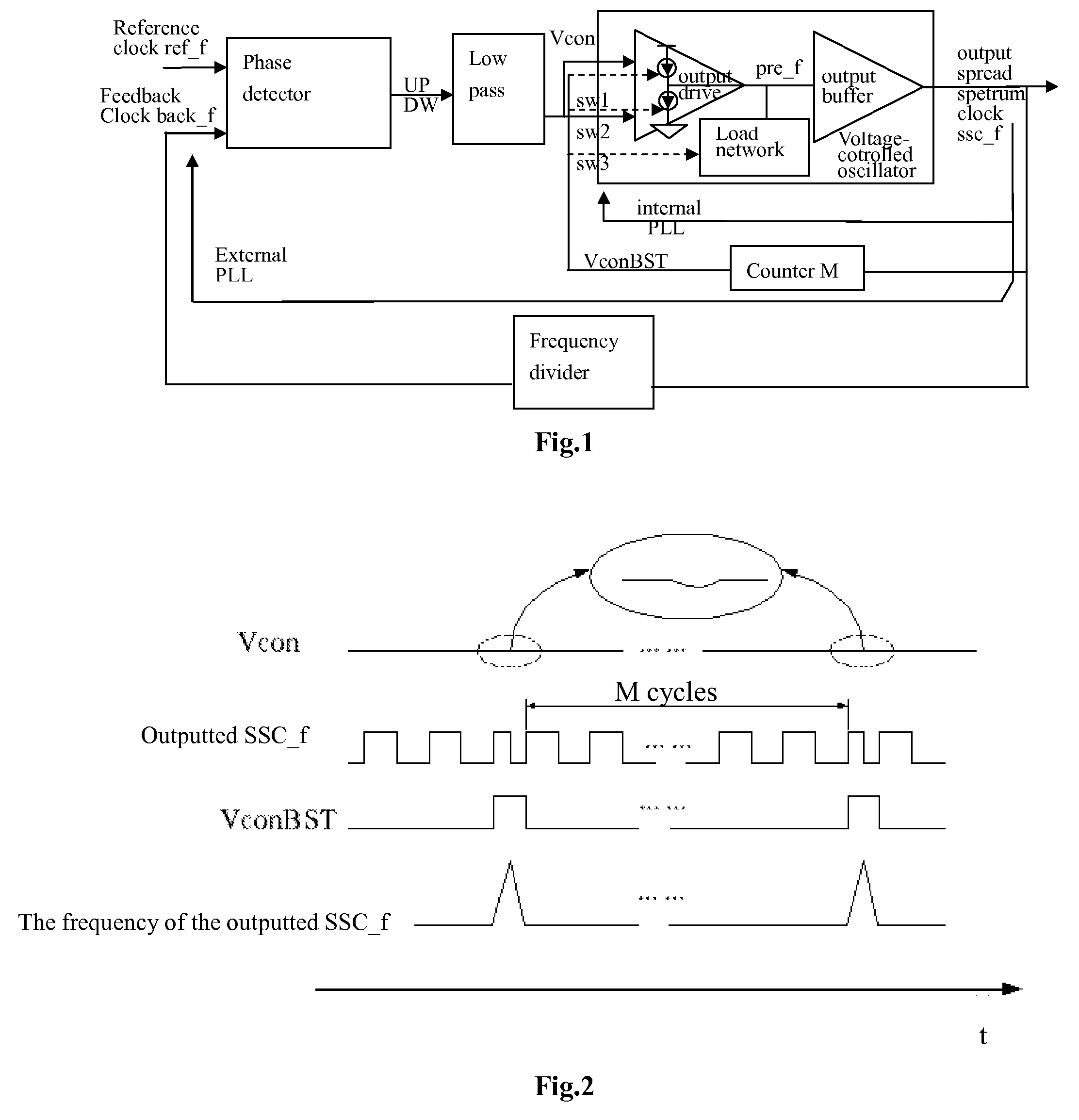
The present invention relates to a spread spectrum clock generating circuit that aims to achieve high accuracy, reduce circuit area and power consumption, and improve reliability. The invention uses a M bit counter as the core part of the internal loop, which has drastically reduced the circuit area and power consumption, compared to conventional spread spectrum circuits. The bigger the current of the current source or current sink of the output drive of the voltage-controlled oscillator, the shorter the rise time of the direct outputting clock, resulting in a bigger frequency. Contrarily, the less the current, the longer the rise time, resulting in a smaller frequency. The load capacity of the load network also affects the frequency. The invention is compatible with conventional PLL, reducing the risk of a new design and improving circuit reliability.

Problems solved by technology

However, the conventional method requires a complicated interpolation circuit with high-accuracy, a delay line circuit with all delay cells matching with each other, a multi-phase judging digital filtering circuit, a high-speed digital multiplexer circuit, and so on.
As a result, the conventional method has led to a very complicated circuit, which in turn has increased the area and power consumption of circuits.
In addition, due to nonlinear attribute of interpolators and delay mismatching of various hierarchies of the delay line circuit, the frequency change of finally obtained spread spectrum clock will be quite non-linear.

Method used


Image

  • Spread spectrum clock generating circuit
  • Spread spectrum clock generating circuit

Examples


Embodiment Construction

[0026]Referring to FIG. 1 and FIG. 2, a spread spectrum clock generating circuit comprises an external phase-locked loop and an internal phase-locked loop.

[0027]Said external PLL comprises of a phase detector, a low-pass filter, a voltage-controlled oscillator and a frequency divider, each of them connecting successively, and the frequency divider connects to the phase detector in order to form an external loop.

[0028]Said internal PLL comprises of the phase detector, low-pass filter and voltage-controlled oscillator of said external PLL, each of them connecting successively, wherein the output terminal of the voltage-controlled oscillator connects with a counter, and the output terminal of the counter connects to an input of the oscillator in order to form an internal loop.

[0029]Said phase detector has two input clock signals, one is a reference clock and the other one is a feedback clock, and two output signals which correspond in phase to the two input signals, UP and DW. The two ...


PUM


Abstract

A spread spectrum generating circuit comprises an external PLL and an internal PLL. The external PLL comprises a phase detector, a low-pass filter, a voltage-controlled oscillator and a frequency divider, each of them connecting successively. The frequency divider is connected to the phase detector in order to form an external loop. The internal PLL comprises the phase detector, the low-pass filter and the voltage-controlled oscillator of the external PLL, each of them connecting successively. An output terminal of the voltage-controlled oscillator connects with a counter, and the output terminal of the counter connects to an input of the oscillator in order to form an internal loop. The present invention is compatible with the conventional ones, and has lower design risk and higher circuit reliability; compared with the general circuit, it has drastically reduced the area and power consumption, which allows more flexible design and meets more demands.

Description

BACKGROUND OF THE PRESENT INVENTION[0001]1. Field of Invention[0002]The present invention pertains to the IC field, more specifically, to a spread spectrum clock generating circuit.[0003]2. Description of Related Art[0004]The spread spectrum clock is applied widely in the integrated circuit system to reduce EMI (Electromagnetic interference).[0005]The general way to obtain a spread spectrum clock is to gate each outputted phase of interpolators in turn, and then reconstruct the clock. However, the conventional method requires a complicated interpolation circuit with high-accuracy, a delay line circuit with all delay cells matching with each other, a multi-phase judging digital filtering circuit, a high-speed digital multiplexer circuit, and so on. As a result, the conventional method has led to a very complicated circuit, which in turn has increased the area and power consumption of circuits. In addition, due to nonlinear attribute of interpolators and delay mismatching of various h...

Claims


Application Information

Patent Timeline
Patent Type & Authority Patents(United States)
IPC IPC(8): H04B1/707
CPCH03K3/84
Inventor WU, GUOSHENGZHANG, ZICHE
Owner IPGOAL MICROELECTRONICS (SICHUAN) CO LTD
Learn More