Inductive plasma chamber having multi discharge tube bridge

a plasma chamber and discharge tube technology, applied in the field of inductive coupled plasma sources and inductive plasma chambers, can solve the problems of poor influence of capacitive coupled plasma methods using electrodes, poor influence of final products, and difficulty in icp technology to obtain high-density plasmas with high uniformity, and achieve high-density plasmas. the effect of increasing the volume of plasma

Active Publication Date: 2013-04-02
NEW POWER PLASMA CO LTD
View PDF7 Cites 8 Cited by
  • Summary
  • Abstract
  • Description
  • Claims
  • Application Information

AI Technical Summary

Problems solved by technology

A capacitive coupled plasma (CCP) method using an electrode has a bad influence upon a final product because impurities are generated from the electrode in contact with plasma.
Capacitive Coupled Plasma (CCP) method using the electrode has a bad influence upon the final product because impurities are generated from the electrode in contact with the plasma.
However, the ICP technology is difficult to obtain high-density plasma having high uniformity only by simply enlarging the size of an inductive coil or a transformer to obtain the plasma having a large volume.
However, it is difficult to obtain high-density plasma with improved uniformity along with a large volume only with a C-shaped bridge to which a transformer proposed in the above-stated technologies is coupled.
Further, if the plasma source comprises a plurality of C-shaped bridges as in these technologies, a gas supply structure for supplying process gases is inevitably designed in a complex structure.

Method used


Image

  • Inductive plasma chamber having multi discharge tube bridge
  • Inductive plasma chamber having multi discharge tube bridge
  • Inductive plasma chamber having multi discharge tube bridge

Examples


Embodiment Construction

[0035]Hereinafter, preferred embodiments of the present invention will be described in detail with reference to the accompanying drawings. However, the present invention is not limited to the embodiments described herein and can be embodied in various forms. The embodiments disclosed herein are provided in order that the disclosure become firm and complete and the spirit of the present invention is sufficiently delivered to those skilled in the art.

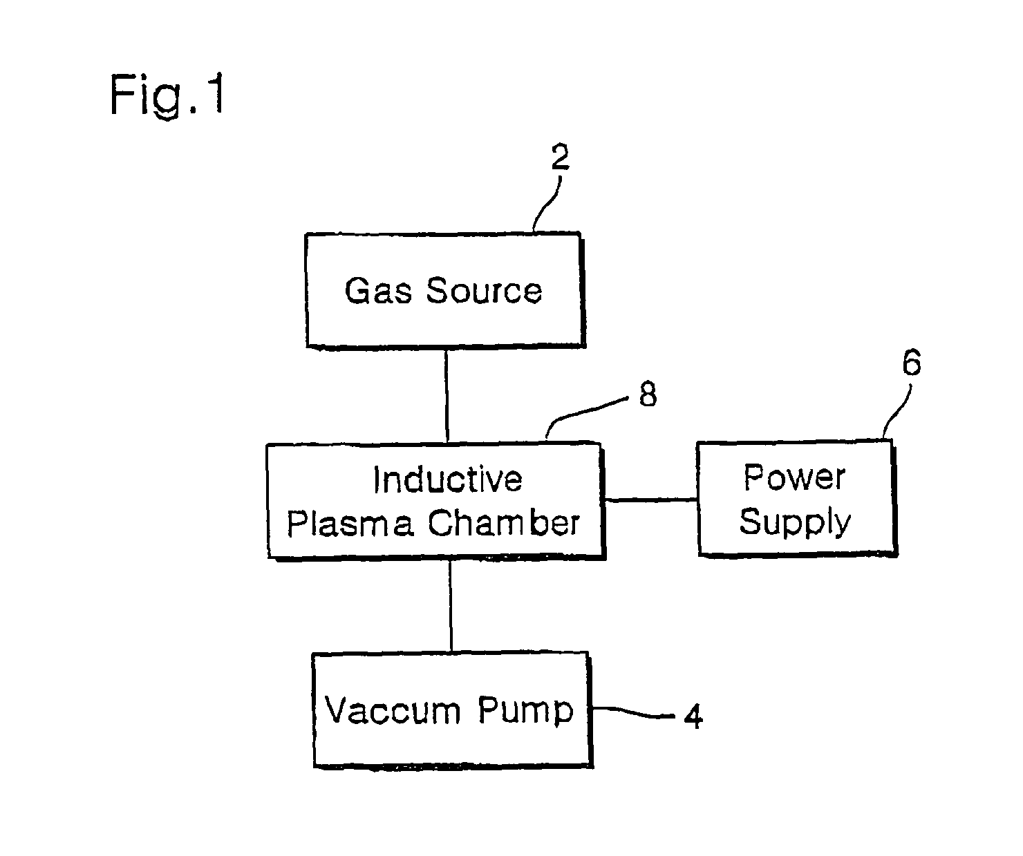
[0036]FIG. 1 is a schematic view showing a construction of a plasma process system using an inductive plasma chamber of the present invention. An inductive plasma chamber 8 of the present invention is connected to introduce discharge gases from a gas source 2, and is connected to vacuum pump 4 to maintain a certain vacuum state. The chamber is supplied with a power supply from the power supply source 6 to generate plasma.

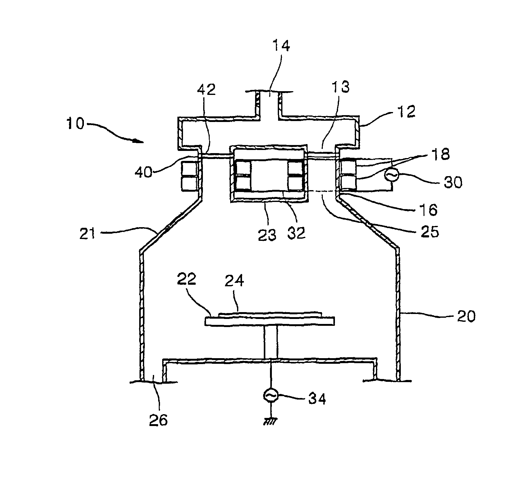
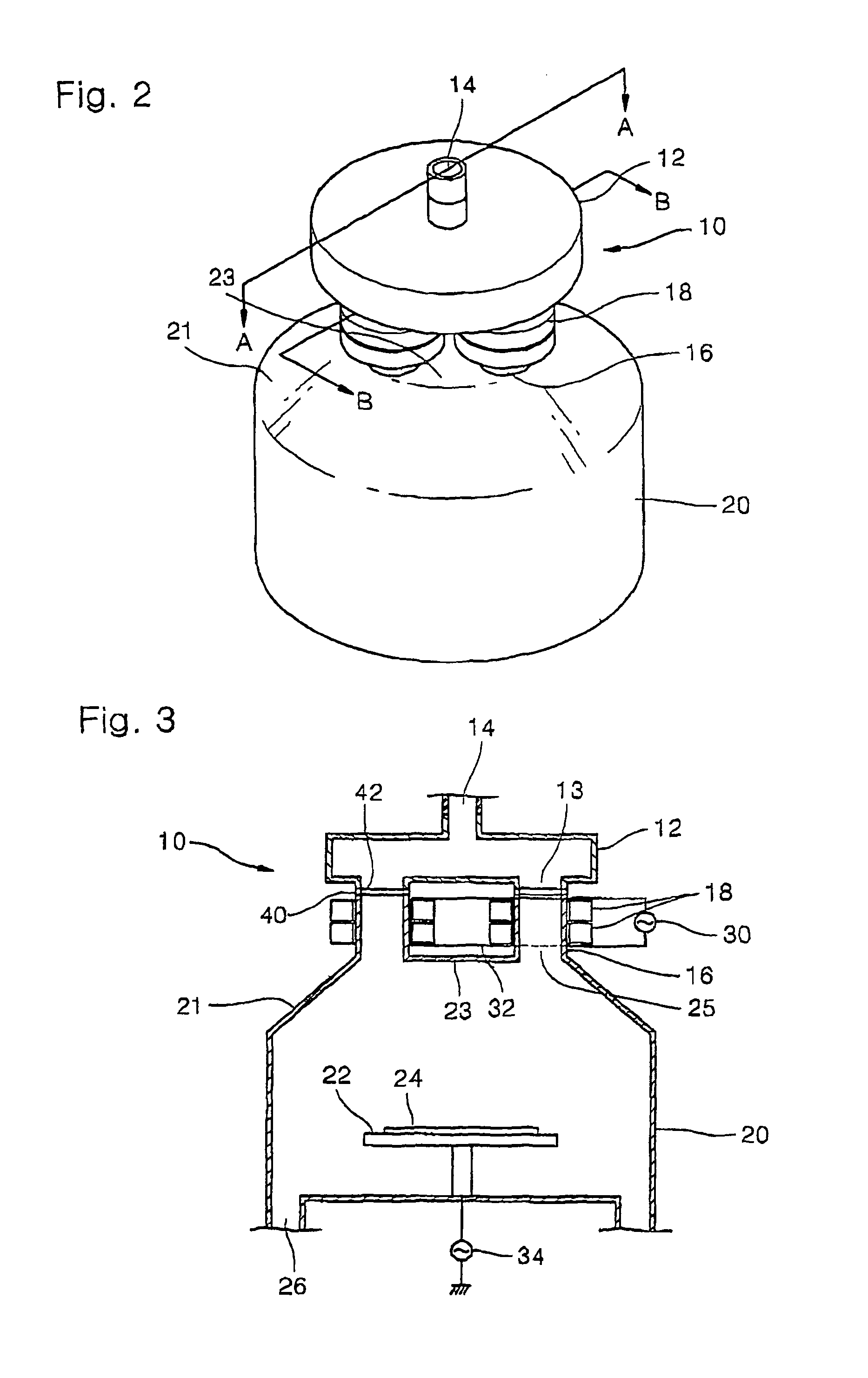
[0037]FIG. 2 is a perspective view of an inductive plasma chamber according to an embodiment of the present invention, ...


PUM

PropertyMeasurementUnit
time periodaaaaaaaaaa
inner diameteraaaaaaaaaa
electromotive forceaaaaaaaaaa

Abstract

An inductive plasma chamber of the present invention comprises a plurality of discharge tube bridges connected between a discharge tube head and a process chamber. The discharge tube head is disc shaped and a cylindrical gas inlet which a gas is injected is disposed in its center. A susceptor on which a workpiece is placed is disposed inside a process chamber and a flange of upper certain area has an inclined surface which is upward centrally inclined. The discharge tube bridge is provided with at least one ferrite core, and the ferrite core has a winding connected to a power supply source. When a process gas is injected via the gas inlet and a RF power from the power supply source is supplied with a winding, the electromotive force is transmitted inside the discharge tube head, the discharge bridge and the process chamber so that the plasma discharge is occurred in the plasma chamber. The plasma chamber comprises a switching means enabling plasma discharge paths to be alternately formed between the plurality of discharge tube bridges. The switching means switches in a predetermined period to be alternately formed the plasma discharge paths between the plurality of discharge tube bridges. The inductive plasma chamber can obtain high-density plasma while enhancing uniformity as well as enlarging plasma volume.

Description

BACKGROUND OF THE INVENTION[0001]1. Field of the Invention[0002]The present invention relates to a plasma source, and more particularly, to an inductive coupled plasma source and an inductive plasma chamber comprising a plurality of discharge tube bridges.[0003]2. Description of the Prior Art[0004]Plasma is a highly ionized gas containing an identical number of positive ions and electrons. At the present time, plasma sources have a variety of applications in several fields. The plasma sources are being used for example for cleaning, etching, deposition, and the like in manufacturing semiconductor devices for producing semiconductor chips.[0005]Generating technologies of inductive coupled plasma (ICP) or transformer coupled plasma (TCP) have been extensively studied in this application field. The RF ICP technology has the advantage that there is no electrode to be in contact with the plasma in providing electro-magnetic energy for generating the plasma. A capacitive coupled plasma (C...

Claims


Application Information

Patent Timeline
Patent Type & Authority Patents(United States)
IPC IPC(8): C23F1/00C23C16/00H01L21/306H01J7/24H05H1/46C23C16/505H01J37/32H01L21/3065
CPCH01J37/321H01J37/32357
Inventor WI, SOON-IM
Owner NEW POWER PLASMA CO LTD
Why Eureka
Try Eureka