Low-swing signaling scheme for data communication

a low-swing signaling and data communication technology, applied in the field of electrical, electronic and computer arts, can solve the problems of reducing the amplitude and signal-to-noise ratio of the received signal, dissipating signal power on the communication channel, and i/o system consuming a significant portion of the overall i/o power, so as to enhance the accuracy of the receiver, reduce the leakage power of the receiver, and high sensitivity

Active Publication Date: 2013-04-02
MEDIATEK INC
View PDF11 Cites 16 Cited by
  • Summary
  • Abstract
  • Description
  • Claims
  • Application Information

AI Technical Summary

Benefits of technology

[0005]Advantageously, aspects of the present invention provide a low-swing signaling scheme and circuits that incorporate a compact low-power receiver with high sensitivity based on gated-diode sensing. This scheme addresses the power and area issues normally associated with low-swing signaling schemes for data communication systems. In addition, embodiments of the invention present circuits to reduce receiver leakage power and an auto-calibration scheme to enhance the accuracy of the receiver by reducing the effect of silicon process variability presented in sub-micron technology on circuit transistors.

Problems solved by technology

Among various circuit blocks in an I / O system, signaling power dissipated on a communication channel established with the I / O system consumes a significant portion of the overall I / O power.
However, low-swing signaling undesirably reduces the amplitude and signal-to-noise ratio of the signal received by a receiver, thereby creating a receiver sensitivity challenge.
Realizing highly sensitive receivers running at multiple Gb / s data rates traditionally results in designs that are complex (and may even demand increased complexity in the transmitter design as well), with an adverse result of increased receiver and / or overall link power and associated area.
However, this type of amplifier consumes considerable power to support high-speed signaling beyond a Gb / s data rate.
264-272, June 2000, a detailed discussion is presented regarding low-swing on-chip interconnection schemes employing receivers that are either complex or consume significant power, making them poorly suited for applications requiring low power and / or compactness.

Method used


Image

  • Low-swing signaling scheme for data communication
  • Low-swing signaling scheme for data communication
  • Low-swing signaling scheme for data communication

Examples


Embodiment Construction

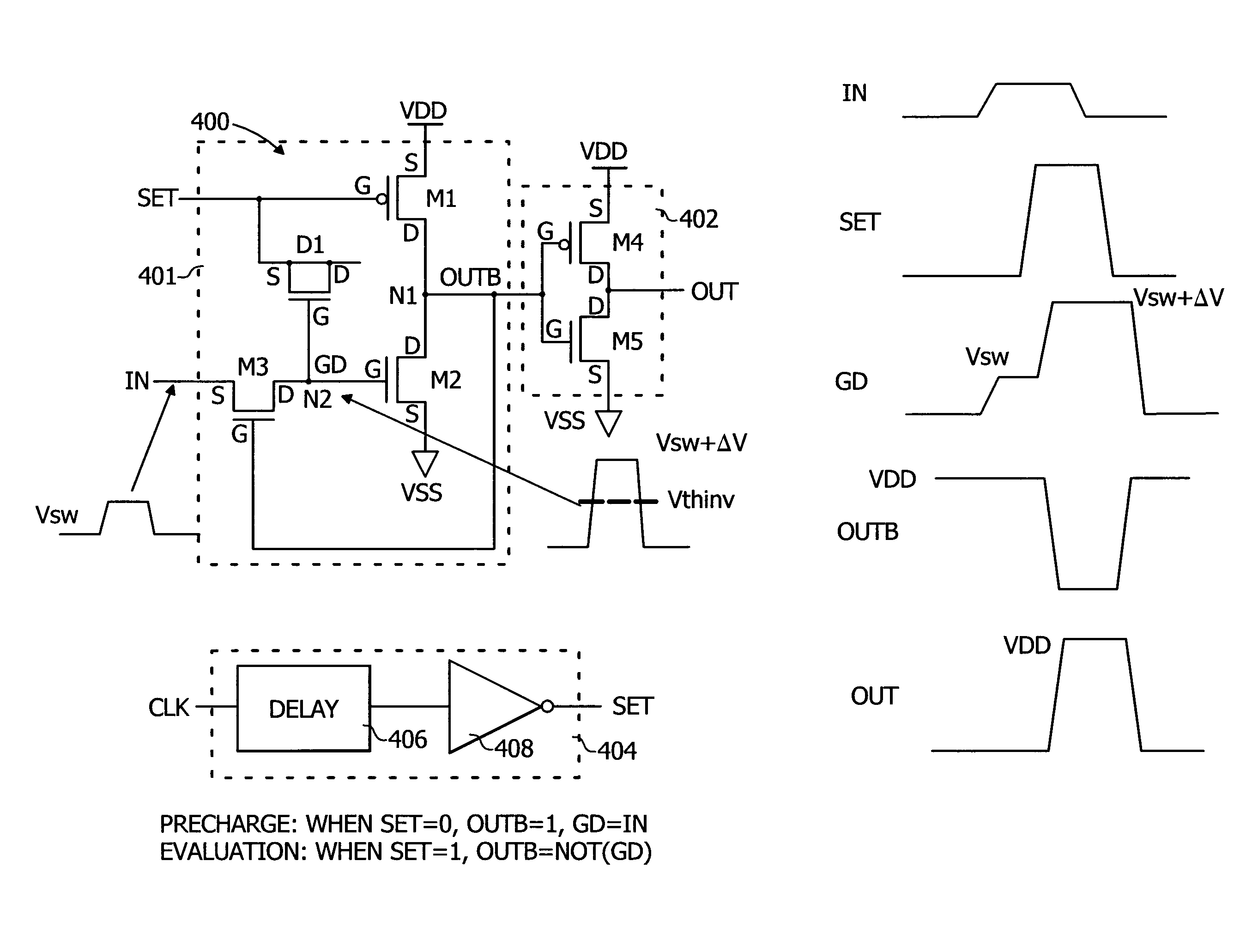
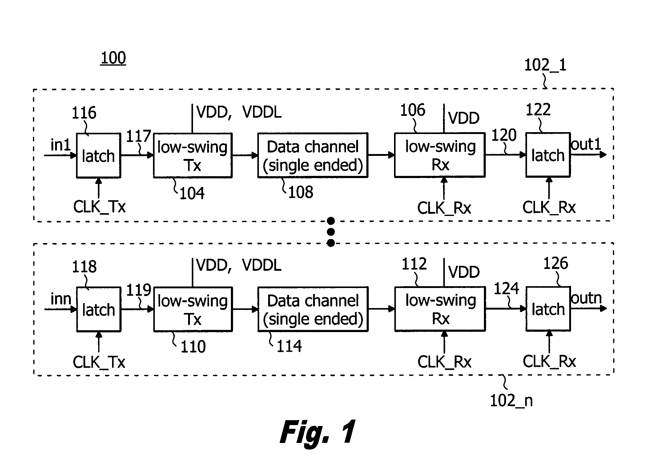
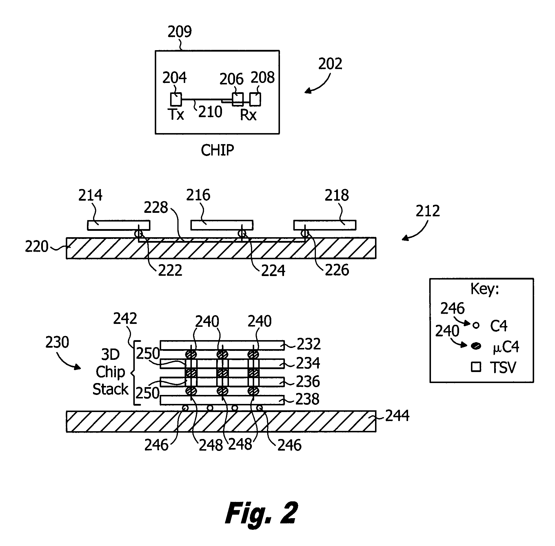
[0020]Embodiments of the present invention will be described herein in the context of illustrative apparatus (e.g., receivers, transmitters, interconnections, etc.) and methods incorporating a compact, low-swing signaling scheme suitable for use, for example, in a data communication system. The term “voltage swing,” or simply “swing,” as used herein is intended to refer to the peak-to-peak output voltage level of a device or circuit; the term “low-swing” is intended to refer broadly to a peak-to-peak output voltage which is much less than prescribed levels (typically, the supply voltage in I / O circuits). It is to be appreciated, however, that the invention is not limited to the specific apparatus and methods illustratively shown and described herein; nor is the invention limited to a data communication system application. Rather, embodiments of the invention are directed more broadly to low-swing signaling techniques for beneficially reducing power consumption and chip area utilizat...


PUM


Abstract

A low-swing receiver includes a sense amplifier including a first transistor having a source connected with a first voltage supply and a gate for receiving a control signal, and a second transistor having a source connected with a second voltage supply, a drain connected to a drain of the first transistor, and a gate coupled to a second control signal via a capacitive element. A switching circuit is operative to selectively couple an input signal supplied to the sense amplifier with the gate of the second transistor as a function of a signal generated at an output of the sense amplifier. The sense amplifier is operative in a first mode to store charge in the capacitive element, and is operative in a second mode to impart a voltage on the gate of the second transistor which is indicative of the charge stored in the capacitive element.

Description

FIELD OF THE INVENTION[0001]The present invention relates generally to the electrical, electronic, and computer arts, and more particularly relates to data processing and communication systems.BACKGROUND[0002]In on-chip and inter-chip data communication systems in which high data bandwidth is required, efficiently managing power dissipation and input / output (I / O) area is crucial. For instance, modern multi-core microprocessors typically have thousands of bits of on-chip data buses connecting processor cores and caches. Similarly, in high-performance servers, inter-chip connections (i.e., links) from processors to network switches or off-chip cache often require I / O buses hundreds of bits wide running at multiple gigabits per second (Gb / s) per-lane data rates. Compact and low-power I / O schemes are needed for these high-performance systems.[0003]Among various circuit blocks in an I / O system, signaling power dissipated on a communication channel established with the I / O system consumes...

Claims


Application Information

Patent Timeline
Patent Type & Authority Patents(United States)
IPC IPC(8): H03K19/094
CPCH03K19/018521
Inventor LIU, YONGLUK, WING KINFRIEDMAN, DANIEL JOSEPH
Owner MEDIATEK INC
Why Eureka
Try Eureka