
Apparatus and methods for carbon dioxide capture and conversion

a carbon dioxide and apparatus technology, applied in the field of apparatus and methods for carbon dioxide capture and conversion, can solve the problems of reducing the cost of electricity generation power plants, most adversely affecting transportation and most global economies, and increasing the burden of atmospheric co2

Active Publication Date: 2013-04-09
ZAROMB SOLOMON
View PDF22 Cites 17 Cited by
  • Summary
  • Abstract
  • Description
  • Claims
  • Application Information

AI Technical Summary

Benefits of technology

The invention aims to capture and use CO2 from the air to create a new fuel that doesn't increase the amount of CO2 in the atmosphere. The process involves using an MgO-loaded cartridge to capture CO2, which is then converted into MgO through a reaction with hydrogen or water. This new fuel can be used to refuel vehicles and other energy-consuming systems. The invention aims to provide an economical and environmentally friendly fuel solution.

Problems solved by technology

State-of-the-art technology using aqueous amines for CO2 capture from flue gas streams produced by existing pulverized coal (PC) burning electricity generating power plants has turned out to be too costly.
According to recent DOE publications, the estimated climax will most likely occur in the year 2016 or at the latest in 2037, after which time impending shortages of petroleum supplies would most adversely impact most forms of transportation and most global economies.
However, a major problem with these sources is the variability of their power generation and the lack of inexpensive ways of storing energy when their available power exceeds usage demands.

Method used


Image

  • Apparatus and methods for carbon dioxide capture and conversion
  • Apparatus and methods for carbon dioxide capture and conversion
  • Apparatus and methods for carbon dioxide capture and conversion

Examples


Embodiment Construction

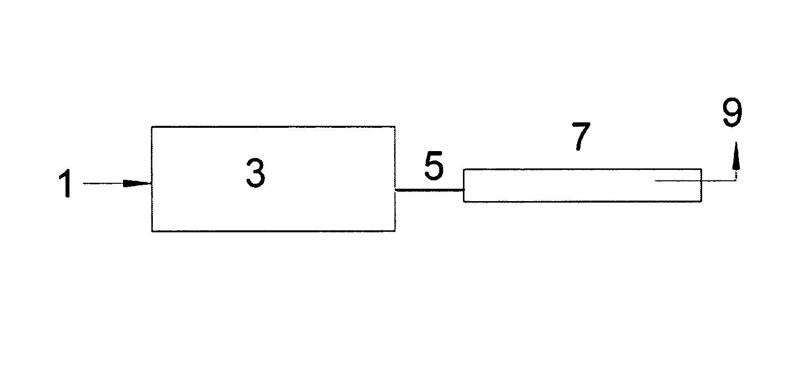
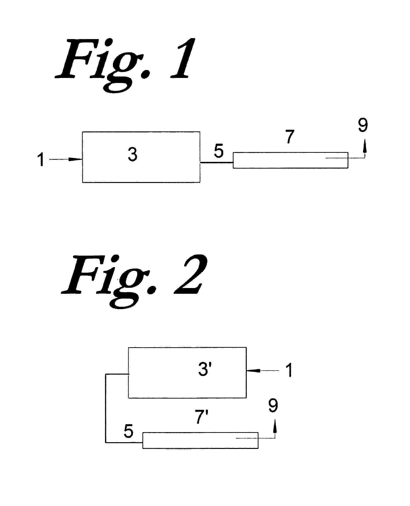
[0026]In the block diagram of FIG. 1, ambient air 1 is partially converted to CO2 in a fossil fuel burning source 3 whose effluents 5 are passed through a CO2 capturing cartridge 7 that is loaded with highly comminuted MgO in a loosely packed fluidized bed. Effluent exit 9 from cartridge 7 may then lead to an exhaust; or to a further cleanup device (not shown) that could remove mercury, nitrogen and / or sulfur oxides and / or other harmful air pollutants; or to a generator of methanol or other useful substance. The comminuted MgO is converted partly to MgCO3 via the carbonation reaction:

[0027]

[0028]Since reaction rates are usually accelerated at higher temperatures, carbonation should occur fastest just below the decomposition temperature of MgCO3, i.e., near 300-350 C.

[0029]In one embodiment of our invention represented by the block diagram of FIG. 2, the fuel burning source 3′ is an internal combustion engine of a motor vehicle and the CO2 capturing cartridge 7′ is contained in a rel...


PUM

PropertyMeasurementUnit
Temperatureaaaaaaaaaa

Abstract

To alleviate and possibly even reverse global warming while providing a liquid fuel to replace petroleum, apparatus and methods are disclosed for capturing CO2 from an air mixture and converting it to a useful substance, especially a methanol-containing fuel, utilizing preferably an MgO-loaded cartridge, which is converted partly into MgCO3 as it captures CO2 by a carbonation reaction and is reconverted into MgO by a calcination reaction while emitting a stream of substantially pure CO2. The emitted CO2 stream is reacted with hydrogen or water to yield a methanol-containing fuel or other useful chemical agent. The hydrogen is preferably derived from water electrolysis using inexpensive solar or wind driven electricity thereby also reducing the cost of such electricity by providing an economical energy storage means. Said air mixture may be the effluent from an internal combustion engine of a motor vehicle or from other fossil fuel burning sources or from the ambient atmosphere. The catalytic combination of hydrogen with CO2 to form methanol can provide a new global environmentally beneficial fuel whose burning will not contribute to any net increase in the atmospheric CO2 burden.

Description

[0001]Applicants claim the benefits of provisional application Nos. 61 / 123,877, filed Apr. 12, 2008, and 61 / 127,854, filed May 17, 2008, both under the same title as above. This invention relates to systems and methods for removing carbon dioxide from air and converting it to an alternative fuel, preferably methanol, so as to alleviate impending global warming and exhaustion of worldwide supplies of petroleum.BACKGROUND OF THE INVENTION[0002]The possibly disastrous consequences of global warming due to increasing atmospheric concentrations of carbon dioxide emanating from the burning of fossil fuels have been widely recognized in recent years, and several solvent- and sorbent-based technologies for capturing CO2 emissions have been explored. State-of-the-art technology using aqueous amines for CO2 capture from flue gas streams produced by existing pulverized coal (PC) burning electricity generating power plants has turned out to be too costly. Analysis conducted at the U.S. Departme...

Claims


Application Information

Patent Timeline
IPC IPC(8): F01N3/08B01D53/62
CPCF01N3/08B01D53/75B01D53/82B01D53/86B01D2251/202B01D2251/402B01D2255/20715B01D2255/2073B01D2255/20761B01D2255/20792B01D2257/504B01D2258/01B01D2258/0233B01D2258/025Y02C10/04F01N2450/30Y02C20/40
Inventor ZAROMB, SOLOMON
Owner ZAROMB SOLOMON
Learn More