Method for dewatering a mixture of mostly ethanol and water

a technology of ethanol and water, applied in the direction of distillation separation, water/sludge/sewage treatment, liquid carbonaceous fuels, etc., can solve the problems of comparatively high energy consumption and chemical use, unoptimized further use, and less robust pervaporation technique with respect to membrane life, etc., to achieve the highest possible operational availability

Active Publication Date: 2013-04-23
EPCON ENERGY & PROCESS CONTROL
View PDF5 Cites 9 Cited by
  • Summary
  • Abstract
  • Description
  • Claims
  • Application Information

AI Technical Summary

Benefits of technology

[0056](**): For molecular sieve the reduction of energy consumption will be less compared to the case of vapour permeation mainly due to the comparatively energy demanding regeneration process.

Problems solved by technology

Industrially water and ethanol often are present in combinations which are not optimal for further use of any one of these compounds.
A comparatively high energy consumption and use of chemicals are characteristic features of this technique.
Pervaporation is a less robust technique with respect to the lifetime of membranes, since the membranes are exposed to possible impurities in the feed.

Method used


Image

  • Method for dewatering a mixture of mostly ethanol and water
  • Method for dewatering a mixture of mostly ethanol and water
  • Method for dewatering a mixture of mostly ethanol and water

Examples


Embodiment Construction

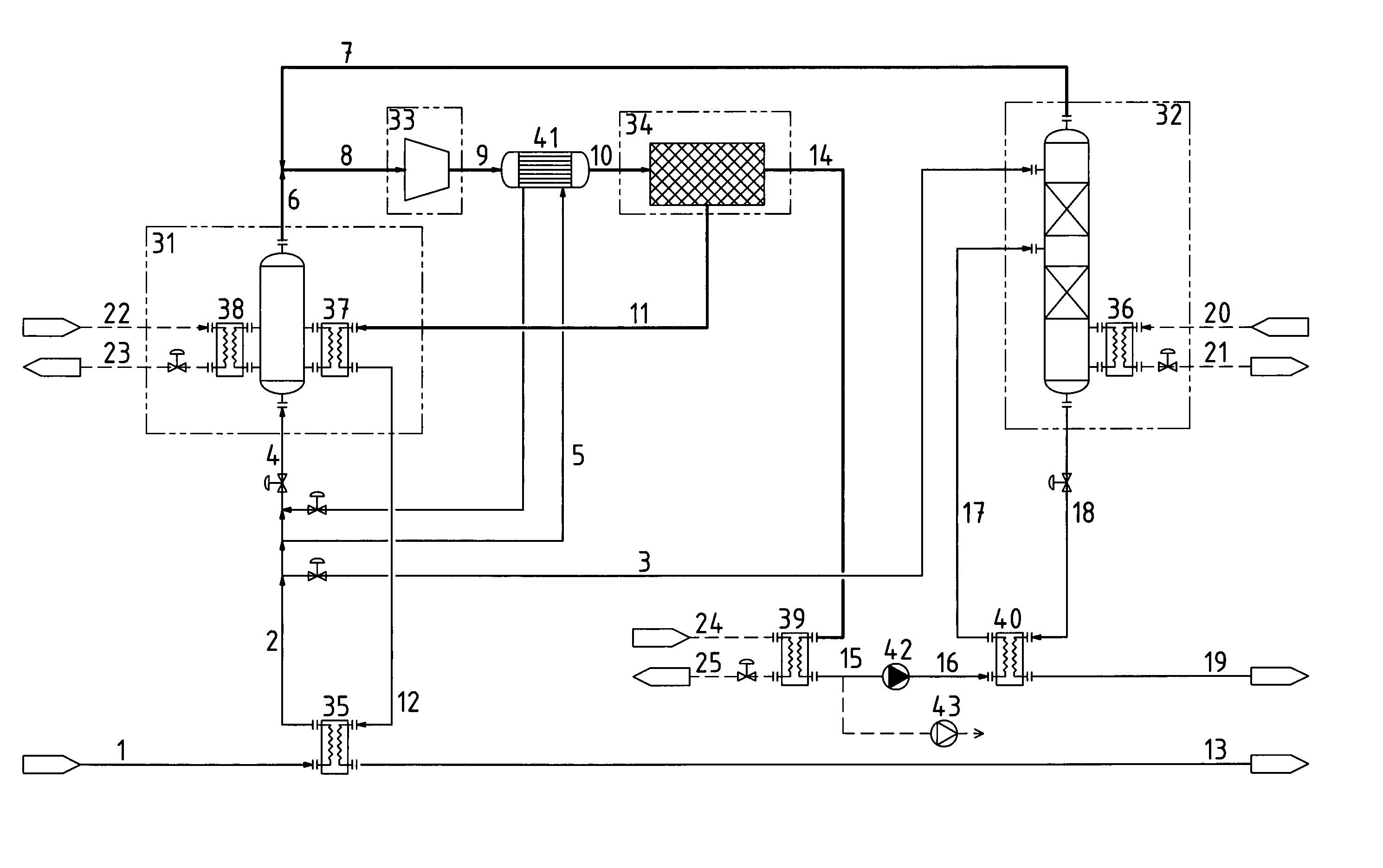
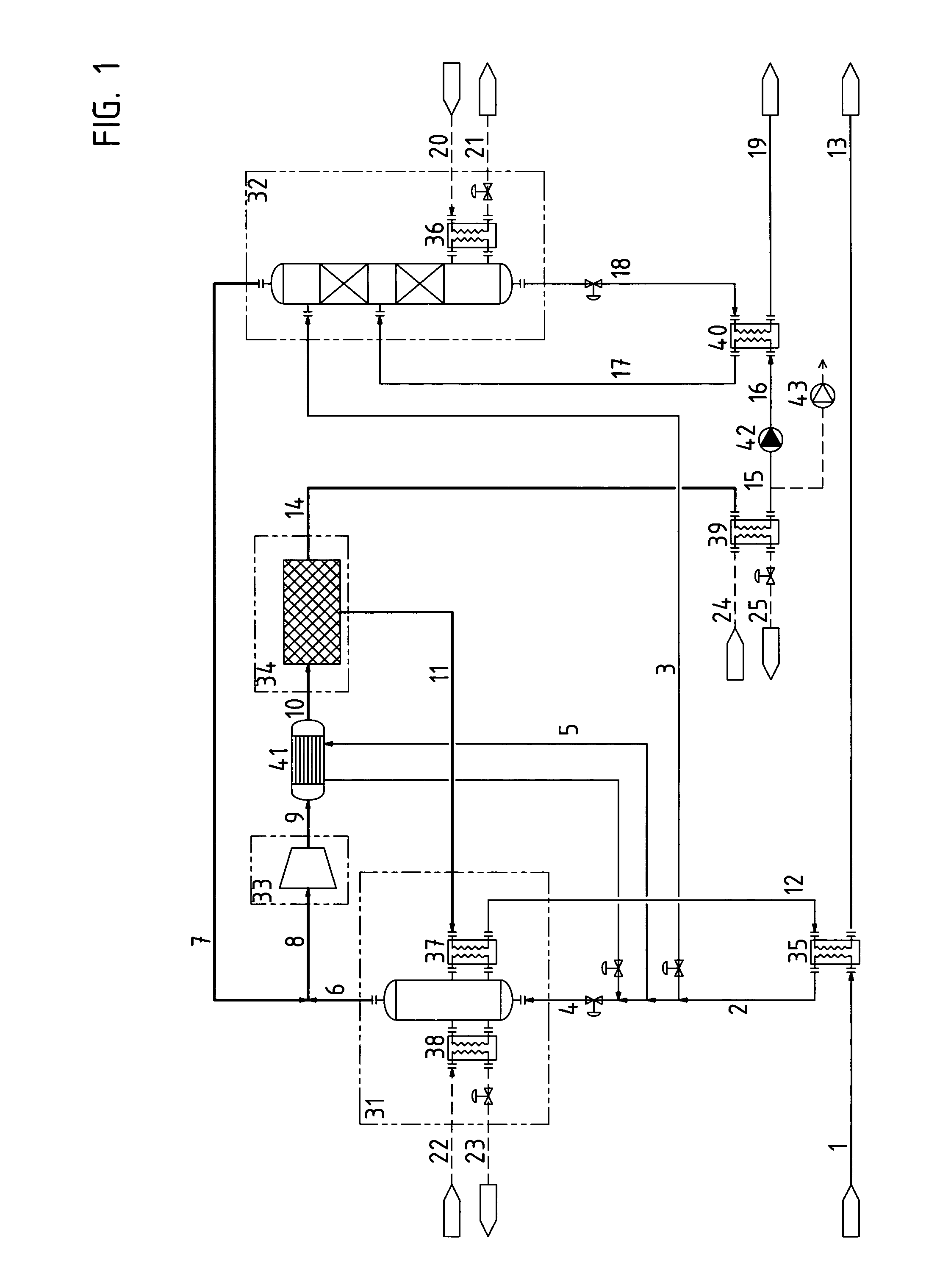
[0018]FIG. 1 is a flow chart of a preferred embodiment of the present invention.

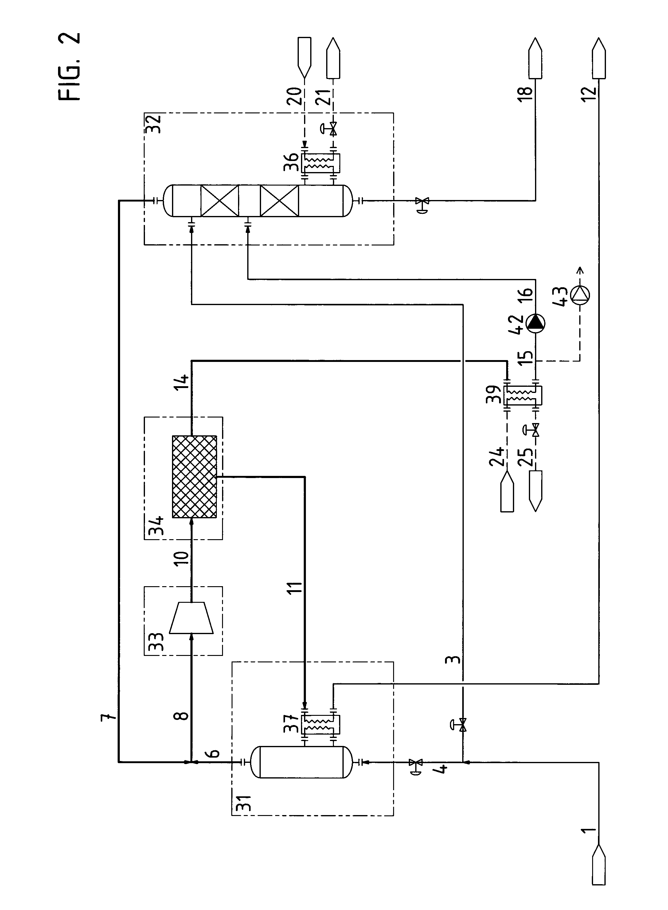
[0019]FIG. 2 is a flow chart of a simpler embodiment of the present invention.

[0020]It should be understood that the exemplification in the form of specific figures below is related to a plant comprising a dewatering unit 34 based on vapour permeation if nothing else is indicated. All indications of relative amounts of process flows are as % by weight unless otherwise specified.

[0021]FIG. 1 shows how a supplied ethanol rich feed flow 1 is preheated in a heat exchanger 35 to a preheated feed flow 2 and thereafter split into a first partial feed flow 3, a second partial feed flow4 with an internal flow 5 that is further preheated in heat exchanger 41. First partial feed flow 3 is charged to a distillation column 32 where it enters as a reflux flow while second partial feed flow 4 enters an evaporator unit 31. First partial feed flow 3 normally corresponds to less than 20% of feed flow 1. The evaporator out...


PUM

PropertyMeasurementUnit
thermal energyaaaaaaaaaa
liquid flowaaaaaaaaaa
energyaaaaaaaaaa

Abstract

Method for dewatering a mixture of mostly ethanol and water which is split into a first partial feed flow (3) that is directed to a distillation column (32) as a reflux flow while a second partial feed flow (4) is directed to an evaporator unit (31) as an evaporator inlet flow and leaves the top of the evaporator unit as an evaporator outlet flow (6). A top discharge flow (7) from distillation column (32) is returned and combined with the evaporator outlet flow (6) to a combined flow (8) at an overpressure and which in a compressor unit (33) is compressed to a combined, compressed flow (10) which enters a dewatering unit (34) in which it is split into a water-rich permeate flow (14) and a retentate flow (11) in the form of substantially water free ethanol. The permeate flow (14) is condensed in a condenser (39) at an underpressure whereafter permeate flow (15) is pressurized by a pump (42) to a flow (16) which is fed to distillation column (32), which is supplied with external thermal energy by a heat exchanger (36), and there split into a water rich bottom discharge flow (18) and an ethanol-rich top discharge flow (7). The retentate flow (11) is used an energy source in a retentate heat exchanger (37) of evaporator unit (31) before leaving as a product flow (12).

Description

[0001]The present invention concerns a method for dewatering a mixture comprising mostly ethanol and water as defined by the characterizing part of claim 1.BACKGROUND[0002]Industrially water and ethanol often are present in combinations which are not optimal for further use of any one of these compounds. Ethanol as a raw material is suitable as a solvent for a plurality of processes or as an energy source. As an example combinations of water and ethanol are present in varying ratios in processes which have as an object to provide substantially water free ethanol as an energy source produced from biological raw materials. In this connection the ethanol is typically referred to as bioethanol.[0003]Traditional distillation process is typically used for the manufacture of ethanol with a water content somewhat higher than the azeotropic point of the composition. In order to reduce the water content of the ethanol / water composition further, to thereby enhance the utility of the ethanol an...

Claims


Application Information

Patent Timeline
Patent Type & Authority Patents(United States)
IPC IPC(8): B01D3/32B01D3/14
CPCB01D3/004B01D3/007B01D3/14B01D3/145B01D3/148B01D53/22B01D61/362C10L1/023B01D61/364C02F1/041C07C29/76C07C31/08B01D61/363C07C29/82C10L1/02
Inventor HALVORSEN, GEIREVENMO, KJETILGOTAAS, CARL IVAR
Owner EPCON ENERGY & PROCESS CONTROL
Why Eureka
Try Eureka