Solid-state image pickup device, method for manufacturing the same, and electronic apparatus
a pickup device and solid-state technology, applied in the direction of electrical equipment, semiconductor devices, radio frequency controlled devices, etc., can solve the problems of reducing light use efficiency and sensitivity, and achieve the effects of low cost, high-quality images, and efficient manufacturing
- Summary
- Abstract
- Description
- Claims
- Application Information
AI Technical Summary
Benefits of technology
Problems solved by technology
Method used
Image
Examples
first embodiment
1. First Embodiment
(A) Structure
(A-1) Structure of Principal Part of Camera
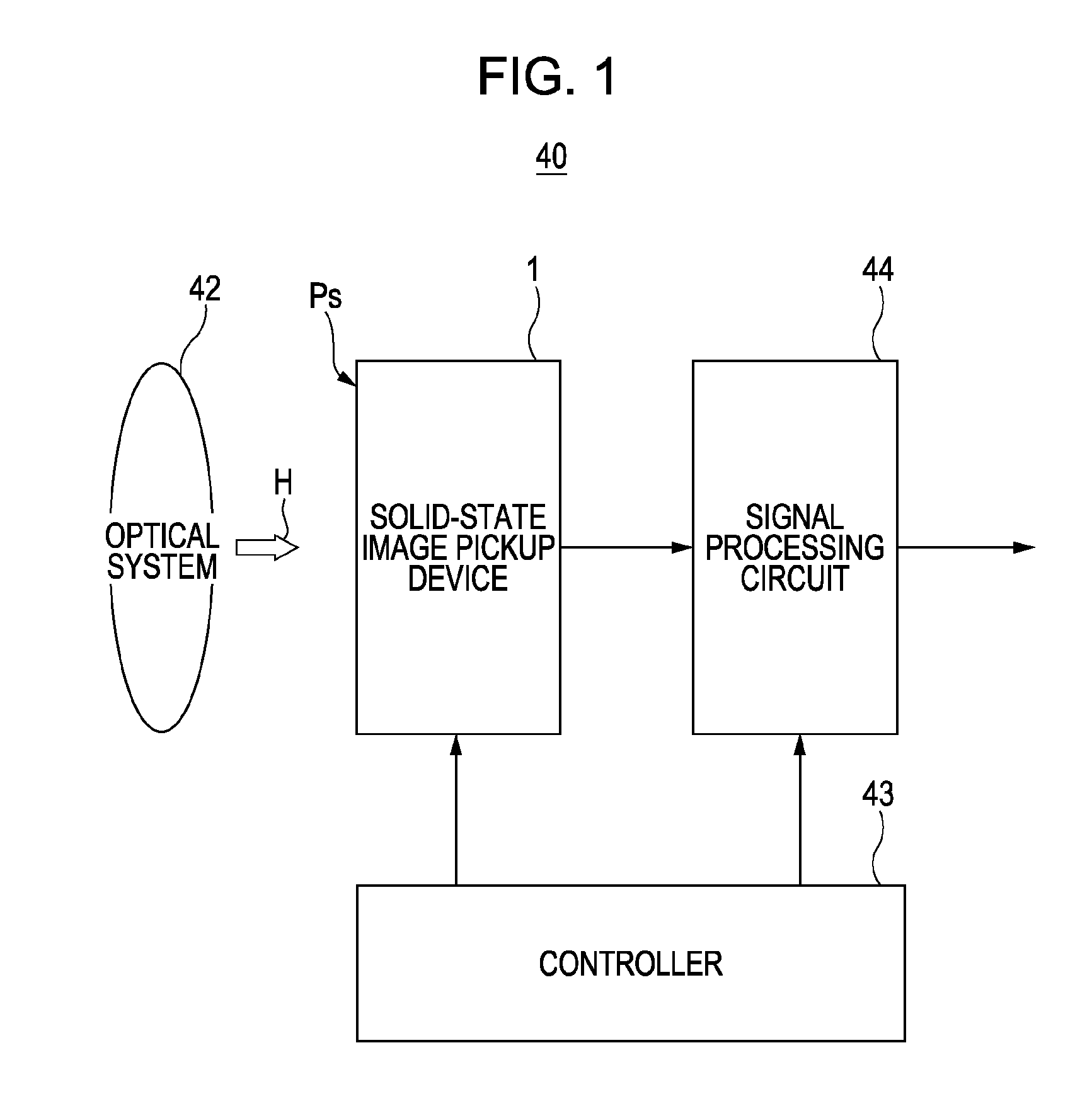
[0055]FIG. 1 is a block diagram of a camera 40 according to a first embodiment of the present invention.
[0056]As shown in FIG. 1, the camera 40 includes a solid-state image pickup device 1, an optical system, 42, a controller 43, and a signal processing circuit 44. These elements will be described one by one.
[0057]The solid-state image pickup device 1 receives light (subject image) H coming through the optical system 42 at an image pickup face Ps and converts the light into electricity to generate a signal charge. In the present embodiment, the solid-state image pickup device 1 is operated according to control signals output from the controller 43. More specifically, the solid-state image pickup device 1 reads out the signal charge and output it as raw data.
[0058]The optical system 42 includes optical members, such as an image-forming lens and an iris, which are arranged so that the light H of the subject ima...
second embodiment
2. Second Embodiment
(A) Structure
[0198]FIGS. 14 and 15 are fragmentary views of a principal part of a solid-state image pickup device according to a second embodiment of the present invention.
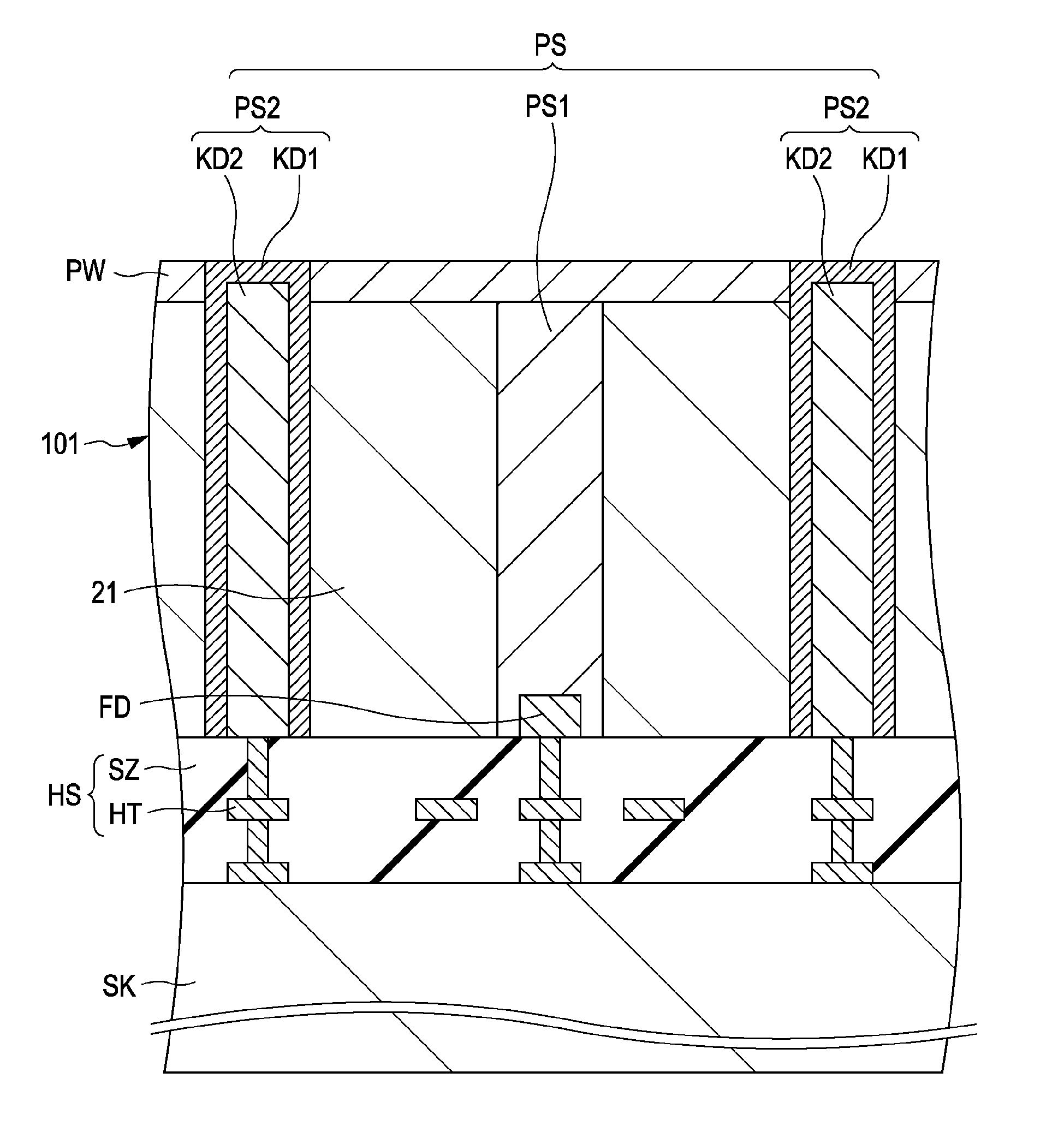
[0199]FIG. 14 is a schematic top view similar to FIG. 3 showing a principal part of an image pickup region PA. FIG. 15 is a schematic sectional view similar to FIG. 4 showing a principal part of the image pickup region PA. FIG. 14 shows the substrate 101 shown in FIG. 15. FIG. 15 shows the section taken along line XV-XV in FIG. 14.
[0200]In the present embodiment, the pixel isolation member PSb is different from that of the first embodiment, as shown in FIGS. 14 and 15. The present embodiment is the same as the first embodiment except for the pixel isolation member, and the same descriptions will be omitted.
[0201]As shown in FIGS. 14 and 15, the pixel isolation member PSb includes a first pixel isolation member PS1 and a second pixel isolation member PS2, as in the first embodiment. Unlike the f...
PUM
 Abstract
Description
Claims
Application Information
 - R&D
- Intellectual Property
- Life Sciences
- Materials
- Tech Scout
- Unparalleled Data Quality
- Higher Quality Content
- 60% Fewer Hallucinations
Browse by: Latest US Patents, China's latest patents, Technical Efficacy Thesaurus, Application Domain, Technology Topic, Popular Technical Reports.
© 2025 PatSnap. All rights reserved.Legal|Privacy policy|Modern Slavery Act Transparency Statement|Sitemap|About US| Contact US: help@patsnap.com


