Optical displacement meter

a technology of optical displacement meter and meter, which is applied in the direction of optical radiation measurement, instruments, measurement devices, etc., can solve the problems of difficult to achieve high speed response difficult high speed response, etc., to achieve high resolving power, high linearity, and high resolving power

Active Publication Date: 2013-04-23
MITUTOYO CORP
View PDF11 Cites 17 Cited by
  • Summary
  • Abstract
  • Description
  • Claims
  • Application Information

AI Technical Summary

Benefits of technology

[0031]The present invention has been conceived to solve the drawbacks of the related art and meets a challenge of enabling accomplishment of high resolving power, high speed response, and miniaturization while taking advantage of merits of a chromatic confocal displacement meter; namely, resistance to an inclination, high linearity, a great working range, a minute measurement spot, and the ability to measure nonmetal.
[0037]According to the present invention, drawbacks of the related-art chromatic confocal displacement meter that cannot accomplish high resolving power and high speed response are surmounted. Measurement of displacement simultaneously satisfying a long working range, a fine measurement spot, a smaller error due to an inclination, high resolving power, and high speed response that have been difficult for a noncontact displacement meter of another type to accomplish becomes possible. Further, in a case that the light receiving element having the small acceptance surface is used, the response speed is improved.

Problems solved by technology

However, under the constrains that the linear array light receiving elements should be used, it has been difficult to accomplish high speed response and high resolving power as follows.
However, since a serial output is produced, exhibition of a high speed response of 1 kHz or more is difficult.
Although a high speed response of tens of kilohertz or more can be accomplished, it is difficult to accomplish high resolving power and high speed response because of a poor signal-to-noise ratio.
However, it is difficult to increase the number of light receiving elements (the number of light receiving elements necessary to accomplish high resolving power is of the order of thousands) by narrowing the pitch of the light receiving elements, and hence difficulty is encountered in accomplishing high resolving power.
Moreover, when a signal processing circuit is provided in number equal to the light receiving elements, a problem of an increase in circuit scale also arises.
However, the electrostatic displacement meter can accomplish high speed response and high resolving power but encounters problems of producing a large measurement spot, providing a short working distance, being vulnerable to an inclination, and generating an error because the displacement meter is a nonconductor.
However, the displacement meter produces drawbacks of being unable to cope with a step and perform ABS measurement, being vulnerable to an inclination, producing a large measurement spot, and being greatly influenced by surface roughness.
The optical fiber displacement meter exhibits high speed response but encounters drawbacks of requiring calibration for each material, producing a large measurement spot, and providing a short working distance.
The triangulation displacement meter exhibits a comparatively superior response but encounters drawbacks of being difficult to exhibit high speed response with high resolving power and being vulnerable to an inclination.
The focusing displacement meter and the confocal displacement meter produce minute measurement spots and provide long working distances but encounter drawbacks of providing low response and a great heat drift.
However, the electrostatic displacement meter and the optical interference displacement meter encounter drawbacks of providing a short working distance, being vulnerable to an inclination, and producing a large measurement spot.
In the case of a transparent substance, difficulty is encountered in distinguishing between a surface and light from the surface.
Therefore, measurement of a thickness of a thin transparent substance that has been possible for the related-art chromatic confocal displacement meter becomes impossible to perform.

Method used


Image

  • Optical displacement meter
  • Optical displacement meter
  • Optical displacement meter

Examples


first embodiment

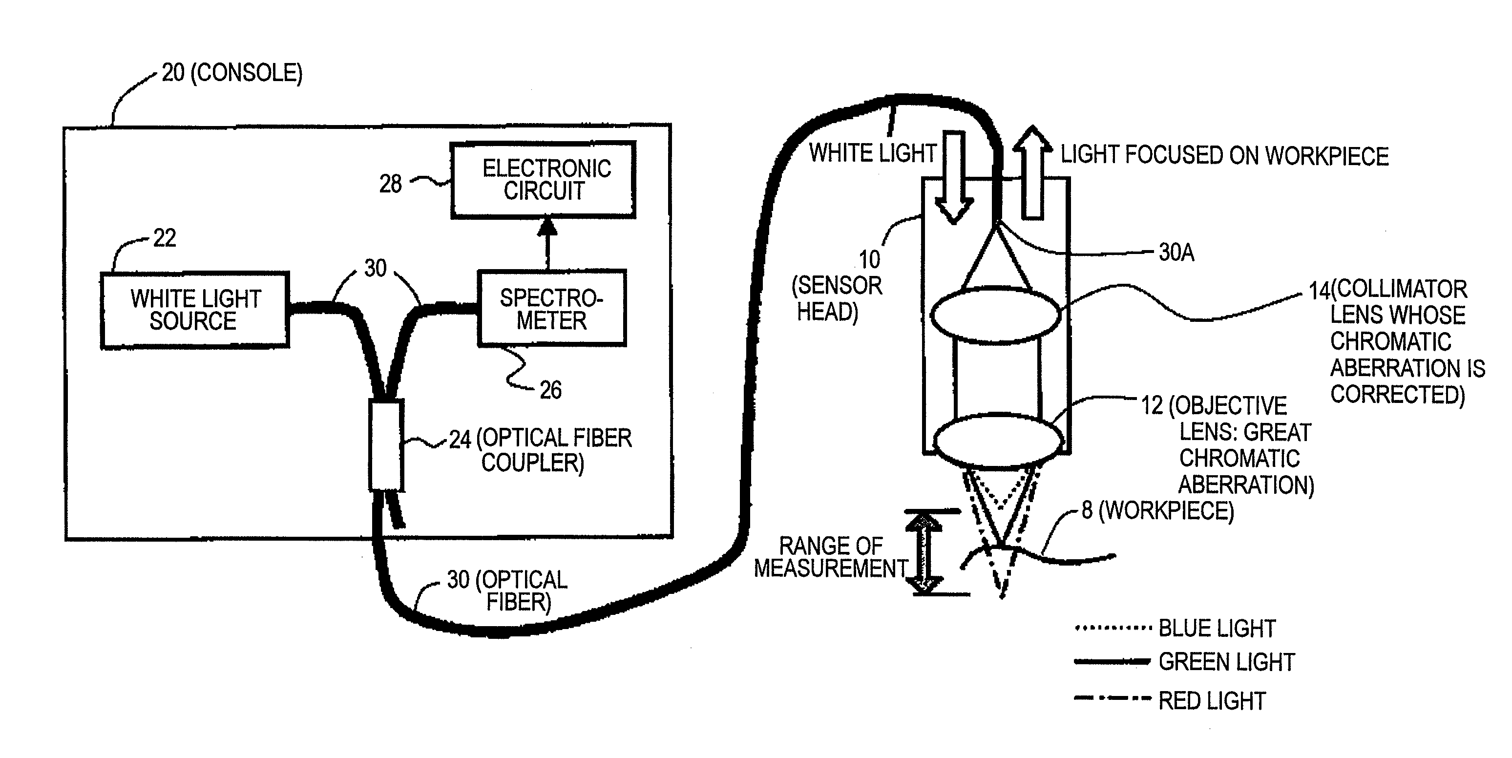
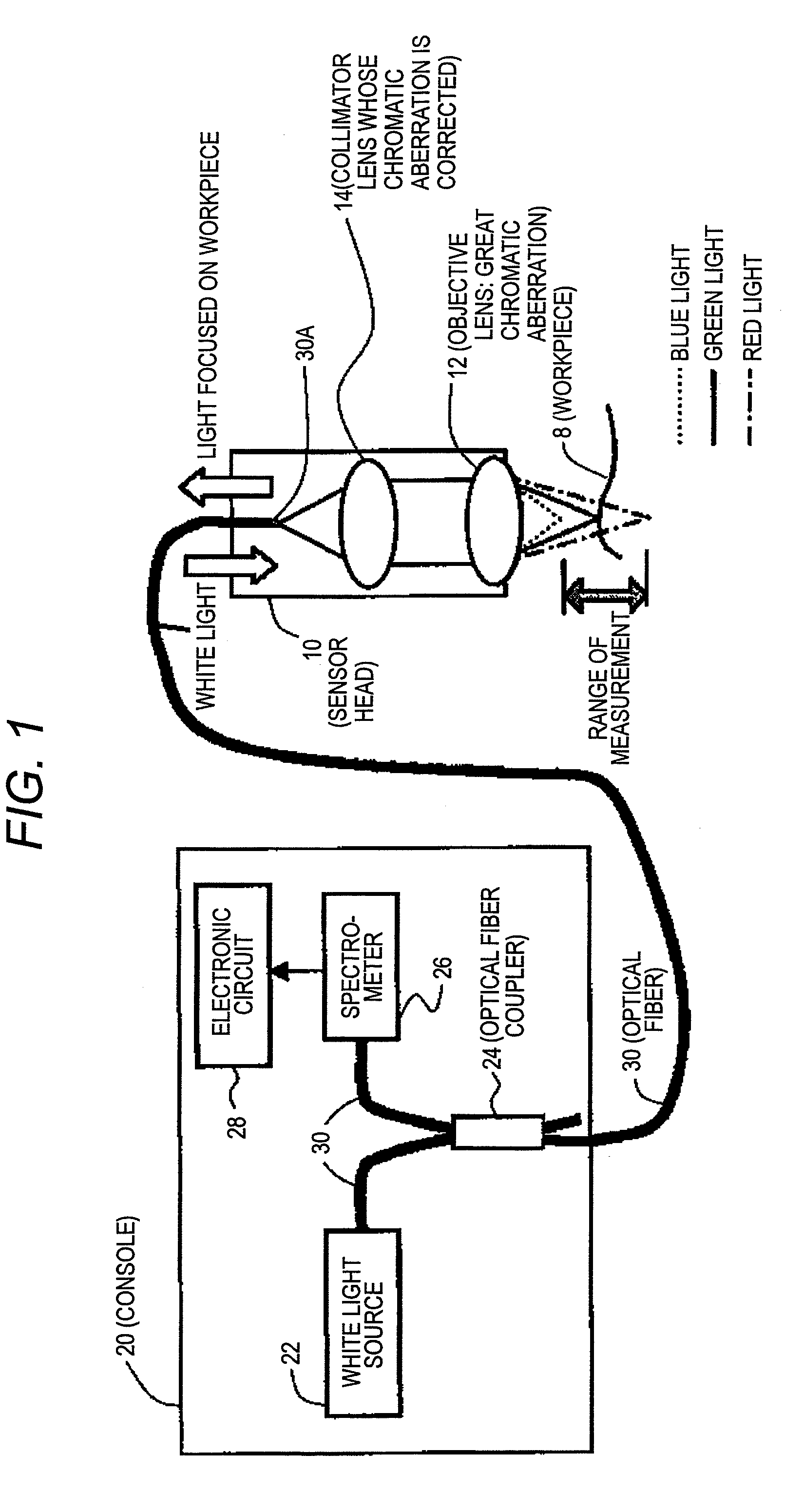
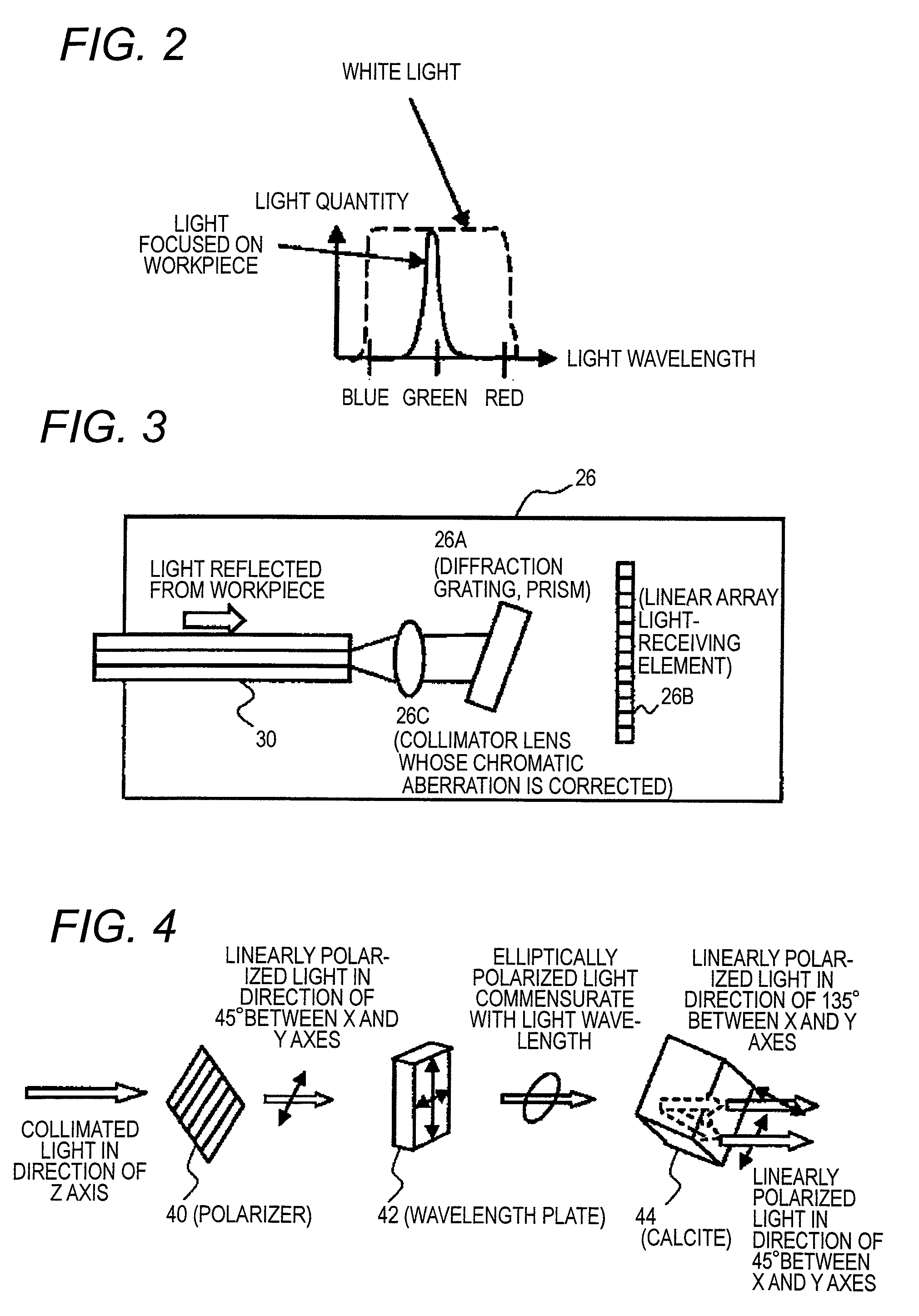
[0069]the present invention is directed toward a chromatic confocal displacement meter having an overall configuration such as that shown in FIG. 1. As shown in FIG. 5, there are used as a spectrometer 26, a collimator lens 50 whose chromatic aberration for collimating light exiting from an optical fiber into parallel light is corrected; a polarizer 52 whose axis for dividing light under measurement collimated by the collimator lens 50 and caused to propagate in one direction (a direction Z) substantially equally into linearly polarized beams of two directions X and Y orthogonal to the propagating direction Z is arranged so as to be oriented in a direction of 45° between X and Y axes; a wavelength plate 54 of the order of zero that allows passage of two linearly polarized light output from the polarizer 52, to thus produce elliptically polarized light having a phase difference between an X-axis polarized wave and a Y-axis polarized wave that is commensurate with a light wavelength; ...

second embodiment

[0090]the present invention that can improve the response speed is described in detail hereunder.

[0091]In a case that a photodiode is used as the light receiving element, a receiver circuit that realizes a high-speed response can be configured by using a photodiode having a little interterminal capacity (electrostatic capacity). Since an electrostatic capacity of depletion layer of p-n junction in the photodiode is proportional to an area of an acceptance surface of the photodiode, the high-speed response can be realized when the acceptance surface is made to small to make the electrostatic capacity smaller.

[0092]According to the chromatic confocal displacement meter of the first embodiment (shown in FIG. 5), the lights received by the photodiodes 58A and 58B are collimated lights as shown in FIG. 18A. When the acceptance surface is smaller than the sectional area of the collimated light, it is necessary to make an incident beam of the acceptance surface thinner. Therefore, in the s...


PUM


Abstract

An optical displacement meter includes: a spatial filter configured to extract light under measurement of a wavelength focused on a measurement target and to specify the wavelength of the light under measurement; a polarizer configured to divide the light collimated and caused to propagate in one direction into linearly polarized beams in two directions orthogonal to a propagating direction; a wavelength plate that allows passage of the linearly polarized beams to produce elliptically polarized light having a phase difference commensurate with a light wavelength; a polarized light separator configured to divide the elliptically polarized light into polarized light components in the two directions; and a computing circuit configured to perform computation of (A−B) / (A+B) by use of light quantity signals A and B, which respectively correspond to the two polarized light components.

Description

CROSS-REFERENCE TO RELATED APPLICATION(S)[0001]This application is based upon and claims the benefit of priority based upon Japanese Patent Application No. 2009-168197, filed on Jul. 16, 2009, and Japanese Patent Application No. 2009-289793, filed on Dec. 21, 2009, the entire contents of which are incorporated herein by reference.BACKGROUND[0002]1. Field of the Invention[0003]The present invention relates to an optical displacement meter and, more particularly, an improvement in a portion for measuring a wavelength of light under measurement that makes it possible to enhance resolving power and high speed response of a chromatic confocal displacement meter and miniaturize the chromatic confocal displacement meter.[0004]2. Description of the Related Art[0005]A chromatic confocal displacement meter (see JP-A-2008-256679) whose entire configuration is shown in FIG. 1 utilizes the following principle. Specifically, an objective lens 12 exhibiting great chromatic aberration along an opti...

Claims


Application Information

Patent Timeline
Patent Type & Authority Patents(United States)
IPC IPC(8): G01J4/00
CPCG01B11/026G01B11/24G01J9/00G02B21/0032G02B21/0064G02B21/0068G01B2210/50
Inventor MIKI, YUTAKA
Owner MITUTOYO CORP
Why Eureka
Try Eureka