
Variable volume clearance pocket for a reciprocating compressor cylinder

a compressor cylinder and variable volume technology, applied in the direction of positive displacement liquid engine, pump components, pump control, etc., can solve the problems of not being physically possible to manually move the variable volume clearing pocket piston, affecting the capacity and required power of the compressor, etc., to achieve the effect of decreasing increasing the clearance volume of the compressor cylinder

Active Publication Date: 2013-04-30
ACI SERVICES
View PDF13 Cites 8 Cited by
  • Summary
  • Abstract
  • Description
  • Claims
  • Application Information

AI Technical Summary

Benefits of technology

Enables safe, accurate, and reliable automatic control of compressor capacity and power consumption, reducing the risk of overload and downtime, while avoiding the drawbacks of hydraulic actuation systems.

Problems solved by technology

Changes in these operating conditions typically affect the capacity and required power of the compressor.
Generally, however, it is not practical and sometimes not physically possible to manually move the variable volume clearancing pocket piston in response to such changes in operating conditions.
First, the internal compression pressures can create large forces that make the clearancing piston difficult to move manually, even with a large wrench or hand-actuated wheel for leverage.
Second, because of vibration and motion of the compressor cylinder during operation, and the operator's need to be close to the operating equipment in order to move the clearancing piston, it is often a dangerous, or at least threatening, proposition to manually move the clearancing piston while the compressor is running.
In fact, many companies do not permit their operators to move the clearancing piston while the compressor is running.
Information such as performance curves or other operating guidance is not often available to the operator to enable a safe resetting of the clearancing piston position while the compressor is operating.
Fourth, few compressors are attended by an operator at all times of the day or night, making it impractical to be aware of the need to move the clearancing piston and then to move the clearancing piston in order to unload or load the compressor.
Fifth, moving the clearancing piston requires breaking loose a typically large jam nut that locks the screw threads on the manual actuator stem and overrides the cyclic loading imposed on the threads by the cyclic compressor cylinder pressure.
In virtually all applications, when compressors shut down unintentionally, revenue is lost.
In some cases the effects of a compressor shutting down at the wrong time can have catastrophic results when the compressor is part of a complex process.
Although this practice provides a conservative operating margin that usually protects the compressor and driver from damage or overloading during upsets, it subsequently results in underloading and underutilization much of the time.
Although there are several automatic variable or so called infinite step devices that are used in some limited applications, these devices tend to be more complicated, more expensive and less reliable than the automatically controlled discrete step devices, making their use less acceptable and less prevalent than the industry's needs otherwise require, especially in light of high energy and compressed product values.
More specifically, automatic variable volume clearancing devices that are hydraulically actuated have major disadvantages that limit their use.
Hydraulic oil is usually not desirable around compressors because of the concern about leaks or ruptures of lines and hoses, which could cause environmental contamination and fires.
In addition, the potential leakage of hydraulic fluid past seals into the process gas is undesirable and often unacceptable.
Finally, hydraulic fluid or other liquids are not perfectly incompressible, especially at higher pressures exceeding about 1000 psig.
This typically results in minute oscillation of the unloader piston and actuating system, leading to premature wear of sealing elements and leakage of process gas or hydraulic fluid that results in downtime, frequent maintenance and risk of environmental contamination.

Method used


Image

  • Variable volume clearance pocket for a reciprocating compressor cylinder
  • Variable volume clearance pocket for a reciprocating compressor cylinder
  • Variable volume clearance pocket for a reciprocating compressor cylinder

Examples


Embodiment Construction

[0036]As defined herein, the term “capacity” means the total flow rate, throughput, or output of a compressor cylinder.

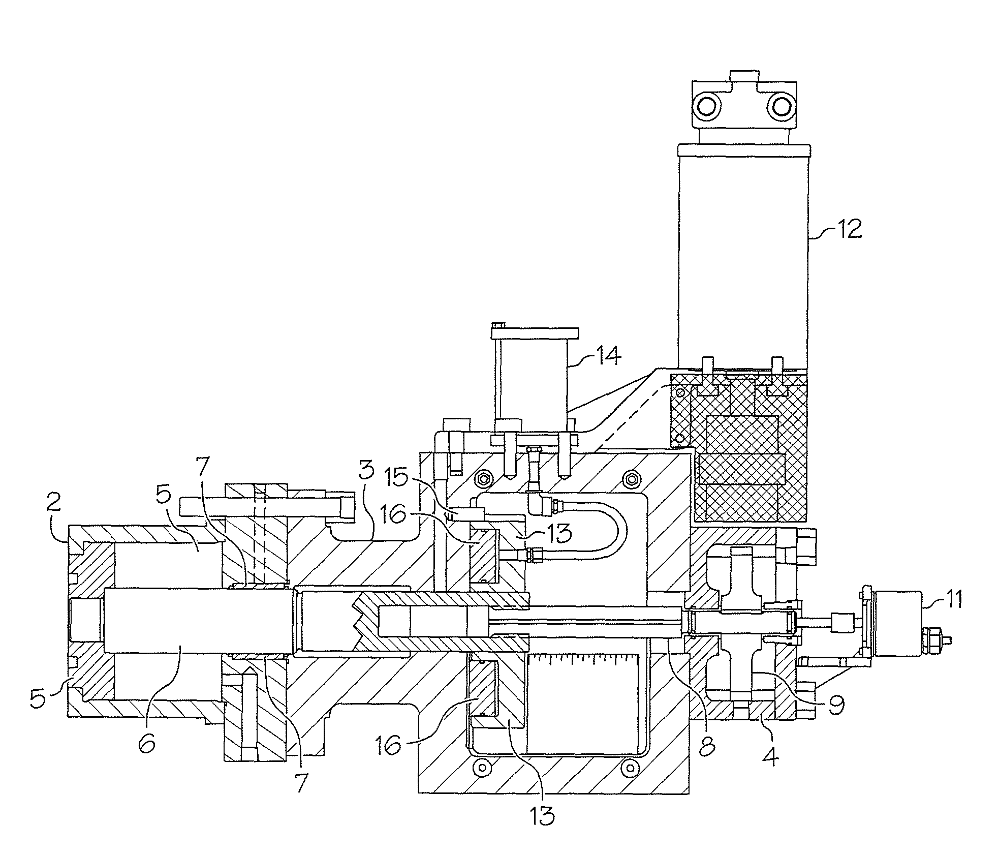
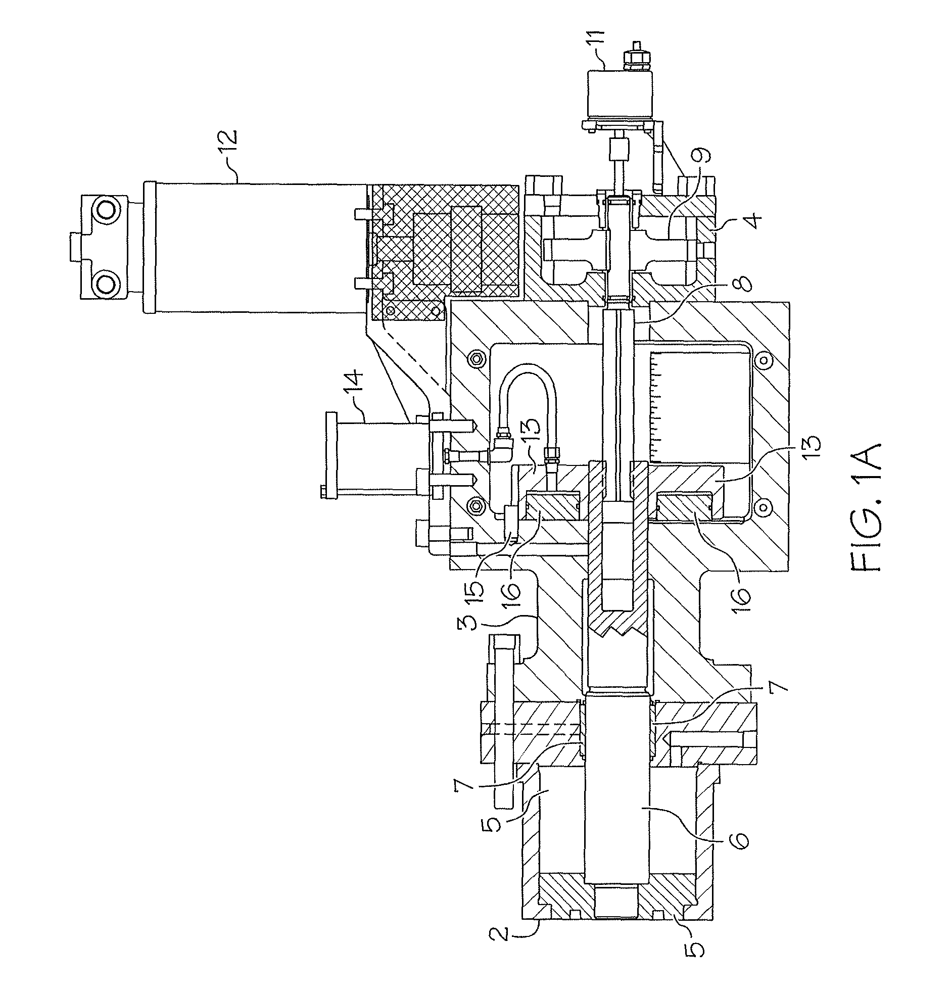
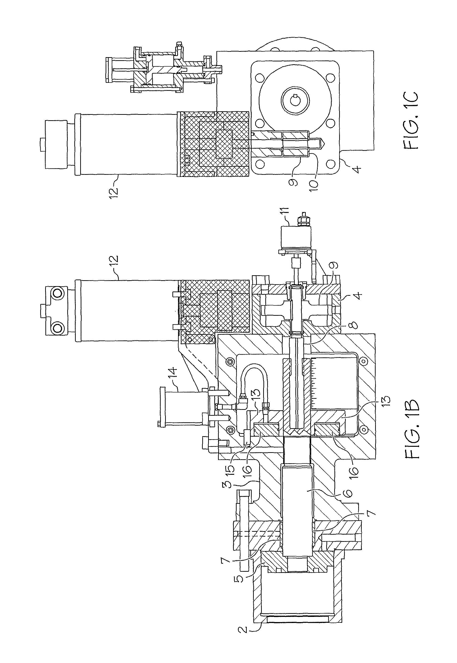
[0037]The present invention is a reciprocating compressor having a controllable variable volume clearance pocket. The compressor includes a device for varying the clearance volume of a variable volume clearance pocket in a controlled manner. The device can be used repeatedly to change the compressor cylinder clearance volume as required or desired, in order to control the compressor capacity and power required from the compressor driver. The device is typically mounted on the outer or head end of a reciprocating compressor cylinder.

[0038]A quick explanation of a few basic thermodynamic principles is necessary to understand the science of reciprocating compressors. Compression occurs within the cylinder as a four-part cycle that occurs with each advance and retreat of the piston (two strokes per cycle). The four parts of the cycle are compression, discharge, expansio...


PUM


Abstract

A controllable variable volume clearance pocket for reciprocating compressor cylinders is disclosed. The invention includes a device for varying the clearance volume of a variable volume clearance pocket in a controlled manner. The device can be used repeatedly to change the compressor cylinder clearance volume as required to control compressor capacity and power required from the compressor driver. The device is typically mounted on the outer or head end of a reciprocating compressor cylinder, but can also be scaled and configured for use either in conjunction with a variable clearance volume unloader operating over a reciprocating compressor valve pocket or a special port in a reciprocating compressor body.

Description

CROSS-REFERENCE TO RELATED APPLICATIONS[0001]This application claims the benefit of U.S. Provisional Application 61 / 088,527, filed Aug. 13, 2008, the disclosure of which is incorporated herein by reference.FIELD OF THE INVENTION[0002]The present invention relates in general to reciprocating compressors, and in particular to reciprocating compressor cylinders having controllable variable volume clearance pockets, and to a device for varying the clearance pocket volume of the compressor cylinder in a controlled manner.BACKGROUND OF THE INVENTION[0003]Reciprocating compressors typically include one or more pistons that “reciprocate” within closed cylinders. They are commonly used for a wide range of applications that include, but are not limited to, the pressurization and transport of air, natural gas, and other gases and mixtures of gases through systems that are used for gas transmission, distribution, injection, storage, processing, refining, oil production, refrigeration, air separ...

Claims


Application Information

Patent Timeline
Patent Type & Authority Patents(United States)
IPC IPC(8): F04B49/00
CPCF04B49/16F04B53/162
Inventor SHADE, W. NORMDOUP, RICHARD
Owner ACI SERVICES
Learn More