Time stretch enhanced recording scope

a time-strength enhancement and recording scope technology, applied in the field of digital representation of electrical signals, can solve the problems of limited high-speed data below about 20 ghz, instruments currently available do not support such high-speed operation, etc., and achieve the effect of reducing the time required

Inactive Publication Date: 2013-04-30
RGT UNIV OF CALIFORNIA
View PDF3 Cites 6 Cited by
  • Summary
  • Abstract
  • Description
  • Claims
  • Application Information

AI Technical Summary

Benefits of technology

[0024]The present invention is an electrical signal measurement system that converts electrical signals in analog format to their digital representation for storage and analysis. A Time Stretch Enhanced Recording (TiSER) oscilloscope is taught for recording a high frequency signal in real time bursts. Signal processing methods are taught for removing distortion in a signal which was digitized using Time-Stretch Analog to Digital Conversion (TS-ADC), and stored thereof. A method is also taught for using the TS-ADC in burst sampling mode, which reduces the time required to measure signal characteristics, such as data bit error rates, and provides useful information about transients of ultra-fast signals that deviate from average behavior. Instruments currently available do not support such high speed operation, and are currently limited to high speed data below about 20 GHz because of the limited bandwidth of existing real-time digitizers.
[0032]In at least one embodiment of the invention the apparatus is used for any of the following: (a) extracting signal information from clock synchronous signals from high speed serial data; (b) determining a bit-error rate (BER) from a high speed serial data stream toward reducing the time required to measure bit-error rate; (c) characterizing emerging high-speed serial data links selected from the group of high speed data links consisting of USB 3.0 targeting 5-Gbit / s serial data rates, PCI-Express at data rates up to 12.5-Gbit / s, OC-768 having data rates up to 43 Gbits / s, and Ethernet OTU4 having data rates up to 100-Gbits / s; (d) performing time-domain reflectometry (TDR) comprising averaging repetitive reflected waveforms over multiple scans toward increasing sensitivity and / or reducing test time; (e) reducing the effect of clock jitter of the electronic digitizer in response to digitizing of the stretched signals at a slower rate than would be required by the input signal being directly digitized; or (f) developing equalization filters and equalization algorithms for compensating for inter-symbol interference (ISI) and other memory effects in received data.
[0041]Another aspect of the invention is an electrical signal measurement system capable of reducing the time to perform signal measurements, including Bit Error Rate (BER), Time Domain Reflectometry (TDR), obtaining inter-symbol information (ISI), generating eye diagrams for serial data, facilitating digital correction of data, data clock recovery, optical carrier phase recovery, and other high speed signal processing activities.

Problems solved by technology

Instruments currently available do not support such high speed operation, and are currently limited to high speed data below about 20 GHz because of the limited bandwidth of existing real-time digitizers.

Method used


Image

  • Time stretch enhanced recording scope
  • Time stretch enhanced recording scope
  • Time stretch enhanced recording scope

Examples


embodiment 2

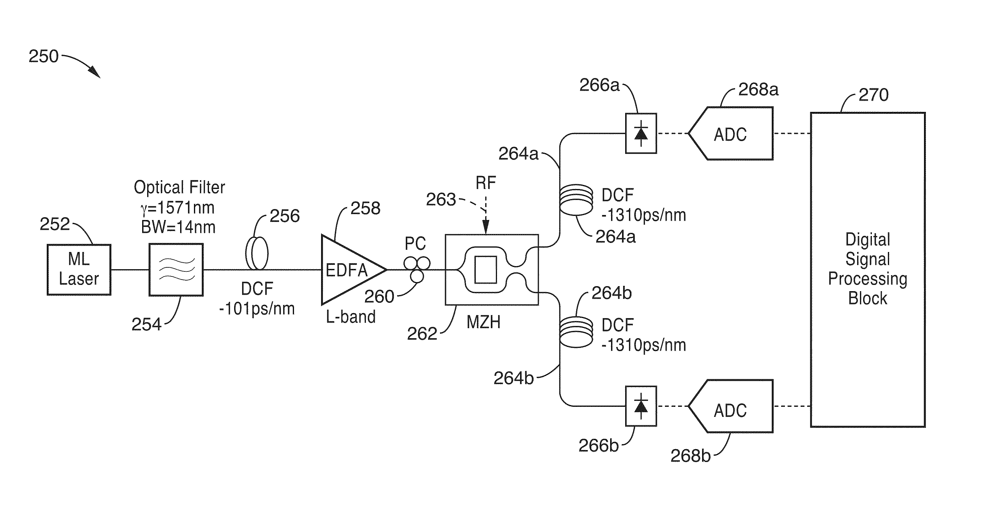
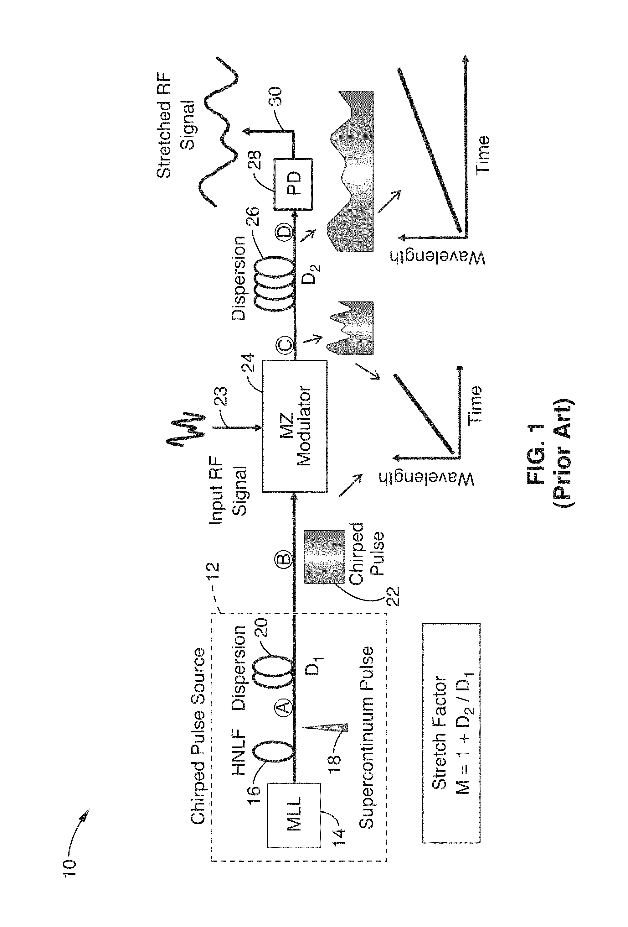
[0131]3. An apparatus as recited in embodiment 2, wherein said pulsed optical source is configured with a mode-locked laser (MLL) coupled through a highly non-linear fiber (HNLF).

[0132]4. An apparatus as recited in embodiment 2, wherein said dispersion element comprises a dispersive optical fiber or a Fiber Bragg Grating (FBG).

[0133]5. An apparatus as recited in embodiment 2, wherein said modulator comprises a modulator selected from the group of modulators consisting of electro-optic modulators, Mach-Zehnder modulators, and electro-absorption modulators.

[0134]6. An apparatus as recited in embodiment 2, wherein said apparatus is configured for receiving high-voltage spikes exceeding approximately 1000 volts without damage, in response to receiving said input within a modulator.

[0135]7. An apparatus as recited in embodiment 2, wherein at least said modulator is separated from the remainder of said apparatus and coupled thereto with an optical fiber; and wherein the remainder of said ...

embodiment 17

[0146]18. An apparatus as recited in embodiment 17, wherein said difference is determined in response to subtracting a negative modulation signal from a positive modulation signal.

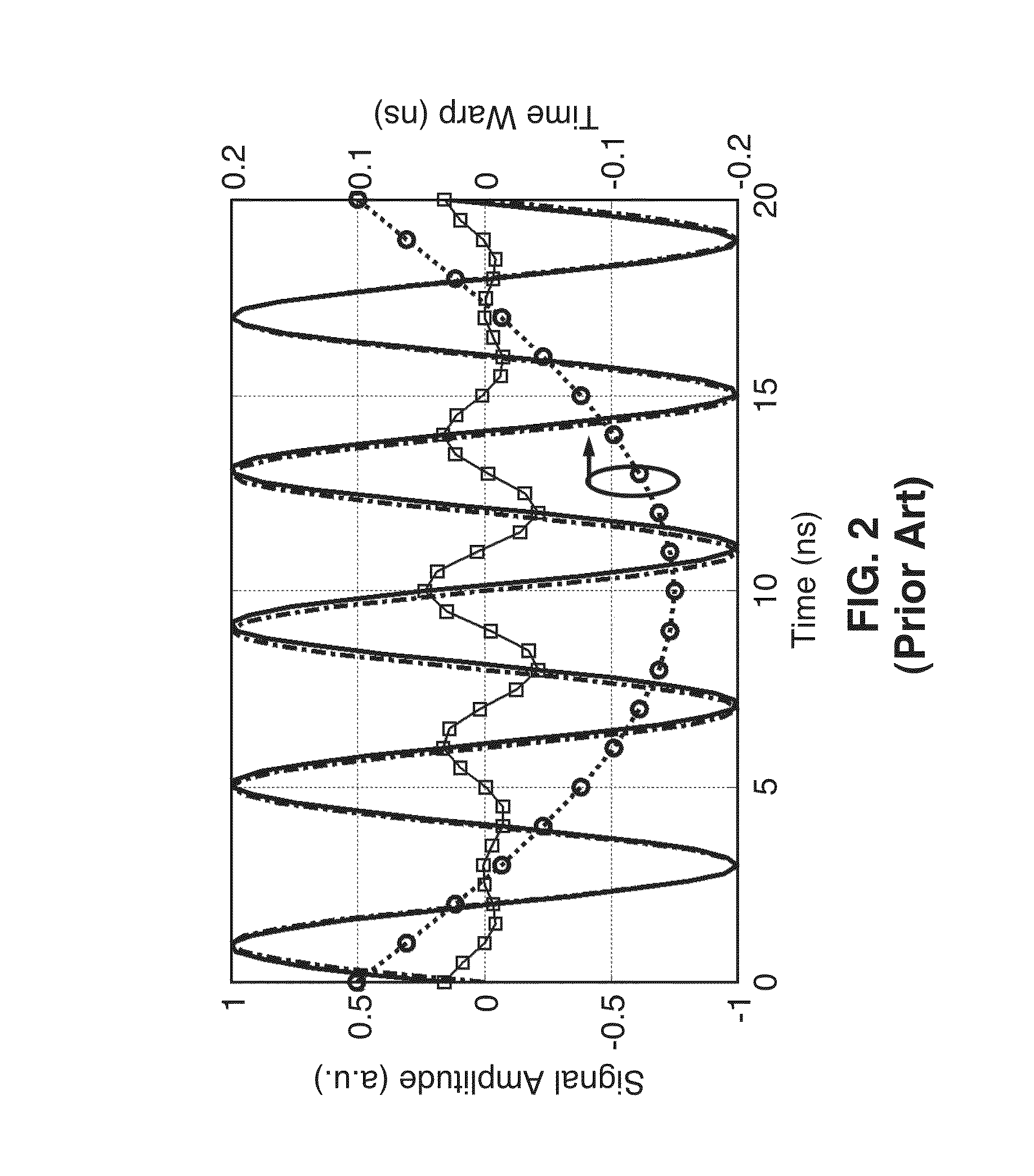
[0147]19. An apparatus as recited in embodiment 2, further comprising programming executable on said processing device for removing time-warp distortion in response to: measuring of time-warp magnitude in response to capturing segments of a sample RF tone subject to a selected modulation, aligning and concatenating any adjacent parallel wavelength channels, fitting the resultant waveform to a curve for the selected modulation, and measuring the difference between the resultant waveform and the selected modulation; and correcting time warp distortion within arbitrary input signals received by said TS-ADC in response to using interpolation of the sample amplitudes.

[0148]20. An apparatus for recovering signals and removing distortion in a photonic Time Stretched Analog-to-Digital Converter (TS-ADC), comprisin...

embodiment 21

[0150]22. A method as recited in embodiment 21, wherein said method is performed within a time-stretched enhanced recording (TiSER) oscilliscope.

[0151]23. A method as recited in embodiment 21, wherein said method provides real-time information about inter-symbol interference (ISI) for said input signal.

[0152]24. A method as recited in embodiment 21, wherein said method determines bit-error rate (BER) of a high speed serial data stream in response to analyzing captured real-time burst samples.

[0153]25. A method as recited in embodiment 21, wherein said real-time burst mode sampling method is configured for digital correction of data impairments.

[0154]26. A method as recited in embodiment 21, further comprising: performing a differential operation on stretched optical pulses; obtaining a maximum and a minimum value for a pulse envelope across multiple pulses; determining envelope size in response to determining a difference between the maximum and minimum pulse envelopes; obtaining co...


PUM


Abstract

A time-stretched enhanced recording scope (TiSER) is described using time stretch analog-to-digital conversion in a real-time burst mode. A chirped optical signal is modulated in response to receiving segments of an input signal. The optical signal with its modulated input signal, is stretched through an optical medium and digitized to represent the waveform segment. TiSER provides ultra-fast real-time sampling within short segment bursts of the original input signal while providing an ability to detect non-repetitive events. Methods and apparatus are also described for providing real-time information about inter-symbol information (ISI), rapidly determining bit-error rates (BER), performing time-domain reflectometry (TDR), generating eye diagrams for serial data, facilitating digital correction of data, clock recovery, optical carrier phase recovery, and otherwise increasing the speed and / or accuracy of a diverse range of high-speed signal measurement and processing activities.

Description

CROSS-REFERENCE TO RELATED APPLICATIONS[0001]This application claims priority to U.S. provisional application Ser. No. 61 / 117,011 filed on Nov. 21, 2008, incorporated herein by reference in its entirety, and to U.S. provisional application Ser. No. 61 / 178,552 filed on May 15, 2009, incorporated herein by reference in its entirety.[0002]This application is also related to U.S. Pat. No. 6,288,659 which is incorporated herein by reference in its entirety.STATEMENT REGARDING FEDERALLY SPONSORED RESEARCH OR DEVELOPMENT[0003]This invention was made with Government support of Grant No. N66001-07-1-2007 awarded by DARPA. The Government has certain rights in this invention.INCORPORATION-BY-REFERENCE OF MATERIAL SUBMITTED ON A COMPACT DISC[0004]Not ApplicableNOTICE OF MATERIAL SUBJECT TO COPYRIGHT PROTECTION[0005]A portion of the material in this patent document is subject to copyright protection under the copyright laws of the United States and of other countries. The owner of the copyright ...

Claims


Application Information

Patent Timeline
Patent Type & Authority Patents(United States)
IPC IPC(8): G01R31/00
CPCG02F7/00G01R13/0218H03M1/1042G02F1/225H03M1/12
Inventor GUPTA, SHALABHJALALI, BAHRAMMOTAFAKKER-FARD, ALI
Owner RGT UNIV OF CALIFORNIA
Why Eureka
Try Eureka