Method of controlling growth and heat loss of an in situ gravity draining chamber formed with a condensing solvent process

a gravity draining chamber and condensing solvent technology, applied in the field of in situ hydrocarbon extraction, can solve the problems of poor confinement, inability to extract hydrocarbon from tightly packed sand formations, and undesirable overburden exposed to condensing solvent in the chamber, so as to maximise the thermal efficiency of the condensing solvent process and extract in situ

Active Publication Date: 2013-05-07
HATCH LTD
View PDF31 Cites 9 Cited by
  • Summary
  • Abstract
  • Description
  • Claims
  • Application Information

AI Technical Summary

Benefits of technology

[0008]What is desired is a method of controlling the location in the gravity drainage chamber where the solvent condensation occurs to control the flow of heat and chamber growth in a condensing solvent process to more efficiently extract in situ heavy oil and bitumen from an oil sand deposit under an overburden layer. In other words, it is desirable, in some circumstances, to preserve the integrity of a layer of bitumen saturated sand at the top of the reservoir in order to provide a confining barrier for the extraction chamber. In other circumstances it is desirable to control the location of condensation in the extraction chamber in order to maximise the thermal efficiency of the condensing solvent process.
[0009]According to the present invention the growth of the extraction chamber in situ can be controlled through the accumulation of non-condensable gases within the extraction chamber that act as a thermal barrier between the condensing solvent on a warm side of said layer, and the overburden or unextracted bitumen on a cold side of said layer. The vapour density of the non-condensable barrier gas, relative to the vapour density of the solvent vapour, at in situ or extraction conditions can be selected to optimize chamber growth and improve extraction effectiveness. By accumulating non-condensable gases having a vapour density which is less than the vapour density of the condensing solvent at extraction conditions, the barrier layer can be preferentially located or floated to a top or attic of a gravity drainage chamber. In this manner, vertical heat flow and vertical chamber growth can be restricted when desired, without stopping continued chamber growth in other directions, such as horizontally along a bitumen layer. By limiting vertical heat flow and vertical growth while encouraging horizontal growth, the horizontal wells may be spaced within the layer to optimise capital costs.
[0015]c. Establishing a non-condensable barrier gas layer at a top of said chamber to reduce the vertical heat flow and vertical growth rate of said chamber at or before said chamber reaches an overburden layer.

Problems solved by technology

These properties make it difficult to extract the hydrocarbon from the tightly packed sand formations in which it is found because unlike lighter oil deposits, heavy oil and bitumen do not readily flow at in situ conditions.
In some cases, the overburden is comprised of the cap rock which can act as a containment layer, but in other cases the overburden may be a sand layer or gravel or other porous material that provides poor confinement.
Where good confinement is available it is preferred to let the chamber grow to all the way to the overburden layer to extract all of the available hydrocarbon, but, leaving the overburden exposed to condensing solvent in the chamber is undesirable.
More specifically, the overburden will continue to attract condensing solvent and the latent heat of condensation of such condensing solvent will be passed to the overburden but to no useful extraction effect.
Therefore, any heat transfer to the overburden layer is wasted, thereby reducing the efficiency of the condensing solvent process.
In some cases, the overburden layer may not be a good confinement layer.
In such a case, if the chamber growth extends vertically to the overburden layer the water will be provided with a pathway into the chamber which could result in the chamber being water flooded.

Method used


Image

  • Method of controlling growth and heat loss of an in situ gravity draining chamber formed with a condensing solvent process
  • Method of controlling growth and heat loss of an in situ gravity draining chamber formed with a condensing solvent process
  • Method of controlling growth and heat loss of an in situ gravity draining chamber formed with a condensing solvent process

Examples


Embodiment Construction

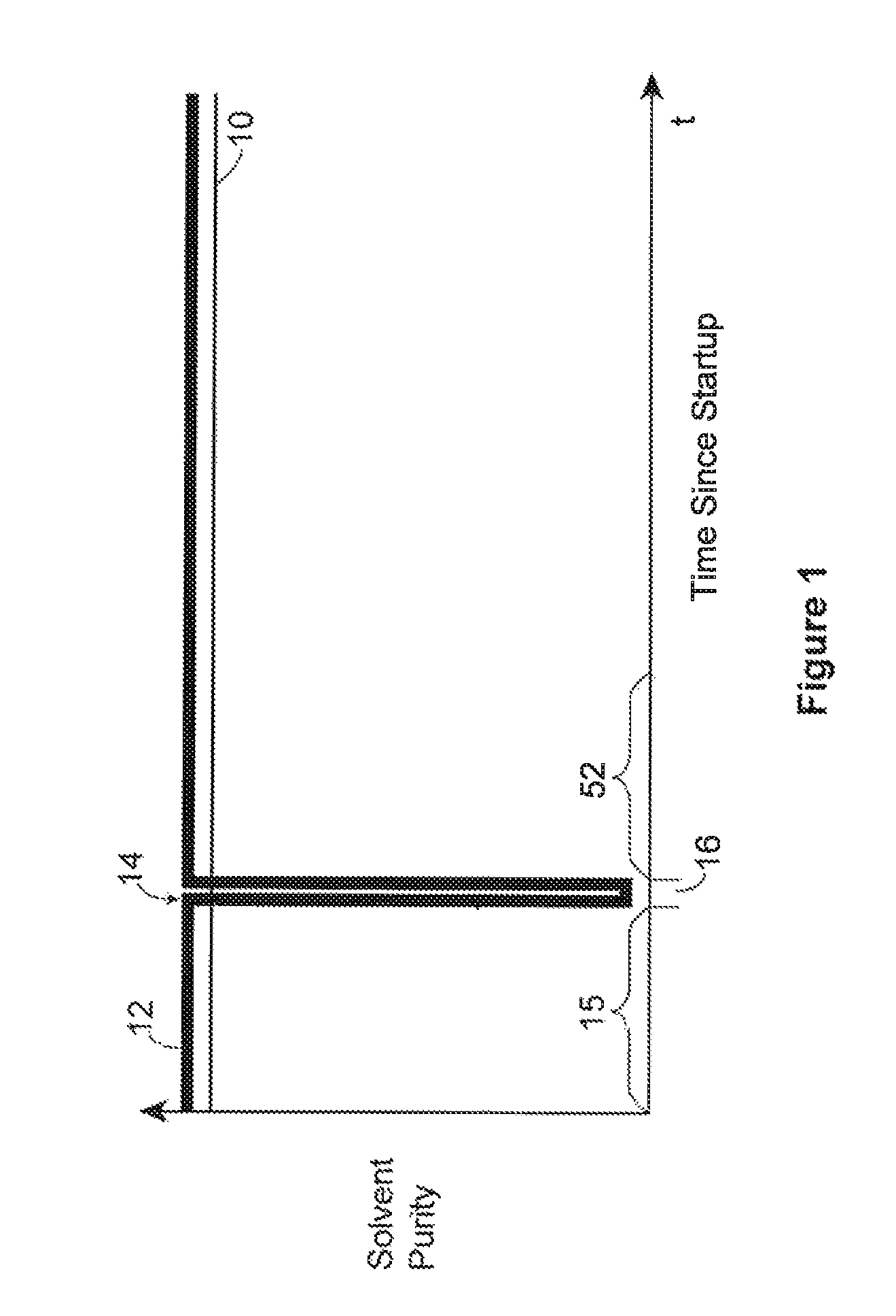
[0027]In FIG. 1, a time line schematic is provided that generally illustrates the trends of purity of the injected condensing solvent over time according to a first aspect of the present invention. The horizontal or x-axis represents time, and the vertical or y-axis represents solvent purity. A horizontal denoted line 10 is also shown, which represents a desired purity of the solvent which is capable of extracting hydrocarbons and bitumen from the formation. This purity is referred to here in as extraction purity since at this purity hydrocarbon extraction occurs. Extraction purity means a solvent that is pure enough to continuously remove non-condensable gases from the chamber. The precise solvent purity required for extraction purity will vary from reservoir to reservoir depending upon in situ conditions such as pressure, temperature and amount of non-solvent gas naturally present and dissolved into the bitumen.

[0028]Also shown is an injected solvent purity line 12, which represen...


PUM


Abstract

A solvent based gravity drainage process whereby the vertical growth rate of the chamber is restricted by placing, monitoring and managing a buoyant gas blanket at the top of the vapor chamber. The process reduces the heat loss to the overburden as well as providing a means to preserve a barrier layer of bitumen saturated reservoir sand at the top of the pay zone in reservoirs where there is limited or no confining layer present.

Description

FIELD OF THE INVENTION[0001]This invention relates generally to the field of in situ hydrocarbon extraction and more particularly to in situ extraction of hydrocarbons by means of a condensing solvent process which mobilizes the hydrocarbons for extraction by, for example, gravity drainage.BACKGROUND OF THE INVENTION[0002]Tar sands or oil sands such as are found in Canada, contain vast reserves of hydrocarbon resources of the type referred to as heavy oil or bitumen. Such heavy oil or bitumen is a hydrocarbon that has a high specific gravity and viscosity. These properties make it difficult to extract the hydrocarbon from the tightly packed sand formations in which it is found because unlike lighter oil deposits, heavy oil and bitumen do not readily flow at in situ conditions.[0003]In prior Canadian Patent No. 2,299,790, a condensing solvent based in situ hydrocarbon recovery process is disclosed. This patent teaches, among other things, using a condensing solvent and controlling th...

Claims


Application Information

Patent Timeline
Patent Type & Authority Patents(United States)
IPC IPC(8): E21B43/24
CPCE21B43/2406E21B43/168E21B43/16
Inventor NENNIGER, JOHNGUNNEWIEK, LOWY
Owner HATCH LTD
Why Eureka
Try Eureka