Monostatic multibeam radar sensor device for a motor vehicle

a multi-beam radar and sensor device technology, applied in measurement devices, instruments, antennas, etc., can solve the problems of significant loss of isolation, significant phase problem, and inability to supply local oscillator power to the receiving channel, so as to broaden the angle estimation range and improve the performance of the participating system

Active Publication Date: 2013-05-14
ROBERT BOSCH GMBH
View PDF31 Cites 23 Cited by
  • Summary
  • Abstract
  • Description
  • Claims
  • Application Information

AI Technical Summary

Benefits of technology

[0005]The monostatic multibeam radar sensor device according to the present invention for a motor vehicle, including a directional characteristic of an antenna unit having at least one transceiving channel and at least one receiving channel, and including a mixer system, which has an at least approximately isolating mixer for at least one of the receiving channels, the at least approximately isolating mixer including a Gilbert cell mixer which, due to a non-ideal isolation of, in particular, its mixer cell, between an input of a local oscillator signal or a local oscillator signal feed and the corresponding receiving channel, emits a transmission power via this receiving channel, using an overcoupling signal, the transmission power influencing the directional characteristic of the antenna unit and the directional characteristic being switchable by controlling the phase position of the overcoupling signal; the monostatic multibeam radar sensor device has the advantage that a switchable directional characteristic or a switchable transmission sum pattern is created. This makes it possible to operate a multibeam radar sensor device having, in particular, two different states which are characterized by transmission sum patterns of different widths. Due to this switching operation, additional information may be obtained which may substantially improve the performance of the participating systems. The switching operation makes it possible to mask out or confirm objects at different angular deviations. In particular, this method appears to be effective within an angle range between 4° and 8°, since significant amplitude differences in the aperture illumination may be expected therein, due to the transmission sum pattern. This may potentially broaden the angle estimation range.
[0009]The inability to control the shift in the phase position of the overcoupling signal may be counteracted as follows. Instead of accepting manufacturing-related differences in the current amplification of the transistors, this parameter may be selectively influenced. Up to now, both differential switching transistor pairs were supplied via a common power source. Dividing the power source into two power sources for the individual switching transistor pairs makes it possible to influence the current amplification of the particular switching transistor pairs, which is co-determined by the injected current. Using a corresponding mimicry and an outer control pin, it is advantageously possible to selectively asymmetrize the current in the two branches. This makes it possible to control a shift in the phase toward 0° or 180°. It must only be ensured that the current difference in the branches is great enough to mask out manufacturing fluctuations.

Problems solved by technology

In the multibeam radar sensor device, this would mean that no supplied local oscillator power could be emitted by the receiving channels, in particular the outer radar beam lobes.
Slight fluctuations in the current amplification result in a significant loss of isolation.
Due to the mixer cell's non-ideal isolation between the input of the local oscillator signal and the corresponding receiving channel, a transmission power is emitted by the overcoupling signal or leakage signal.
A significant problem arose with regard to the phase.

Method used


Image

  • Monostatic multibeam radar sensor device for a motor vehicle
  • Monostatic multibeam radar sensor device for a motor vehicle
  • Monostatic multibeam radar sensor device for a motor vehicle

Examples


Embodiment Construction

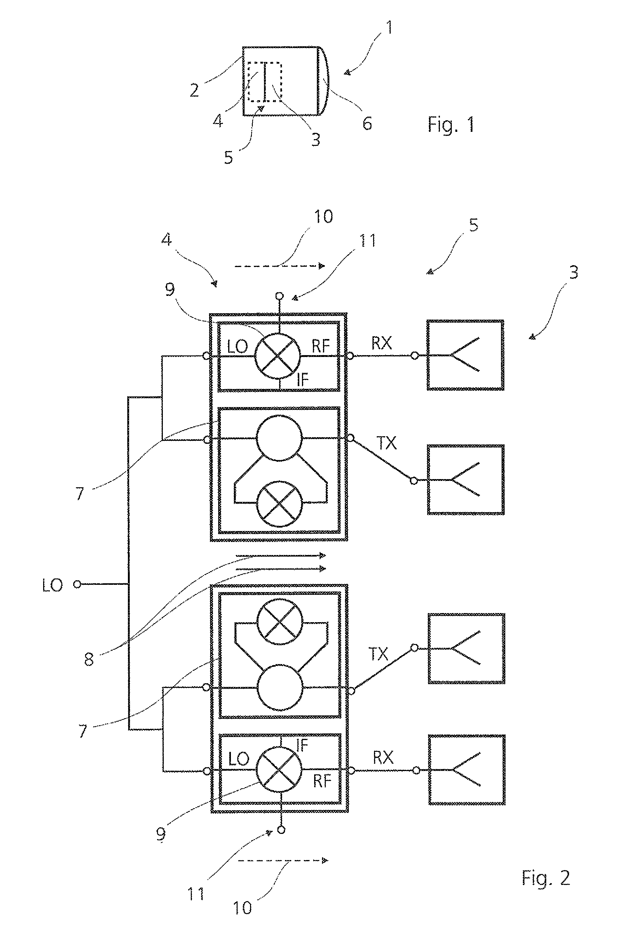
[0018]FIG. 1 shows a monostatic multibeam radar sensor device 1 according to the present invention for a motor vehicle (not illustrated), including a housing 2. Housing 2 includes an antenna unit 3 and a mixer system 4, which form a receiver architecture 5 of multibeam radar sensor device 1 according to the present invention, including transceiving channels TX and receiving channels RX (see FIG. 2). A beam forming element designed as a lens 6 is also provided.

[0019]Transceiving channels TX and receiving channels RX of multibeam radar sensor device 1 result in a directional characteristic of multibeam radar sensor device 1, including radar beams or radar beam lobes B1, B1′ through B4, B4′, which add up to corresponding transmission sum patterns Σ, Σ′ (see FIGS. 4 and 5).

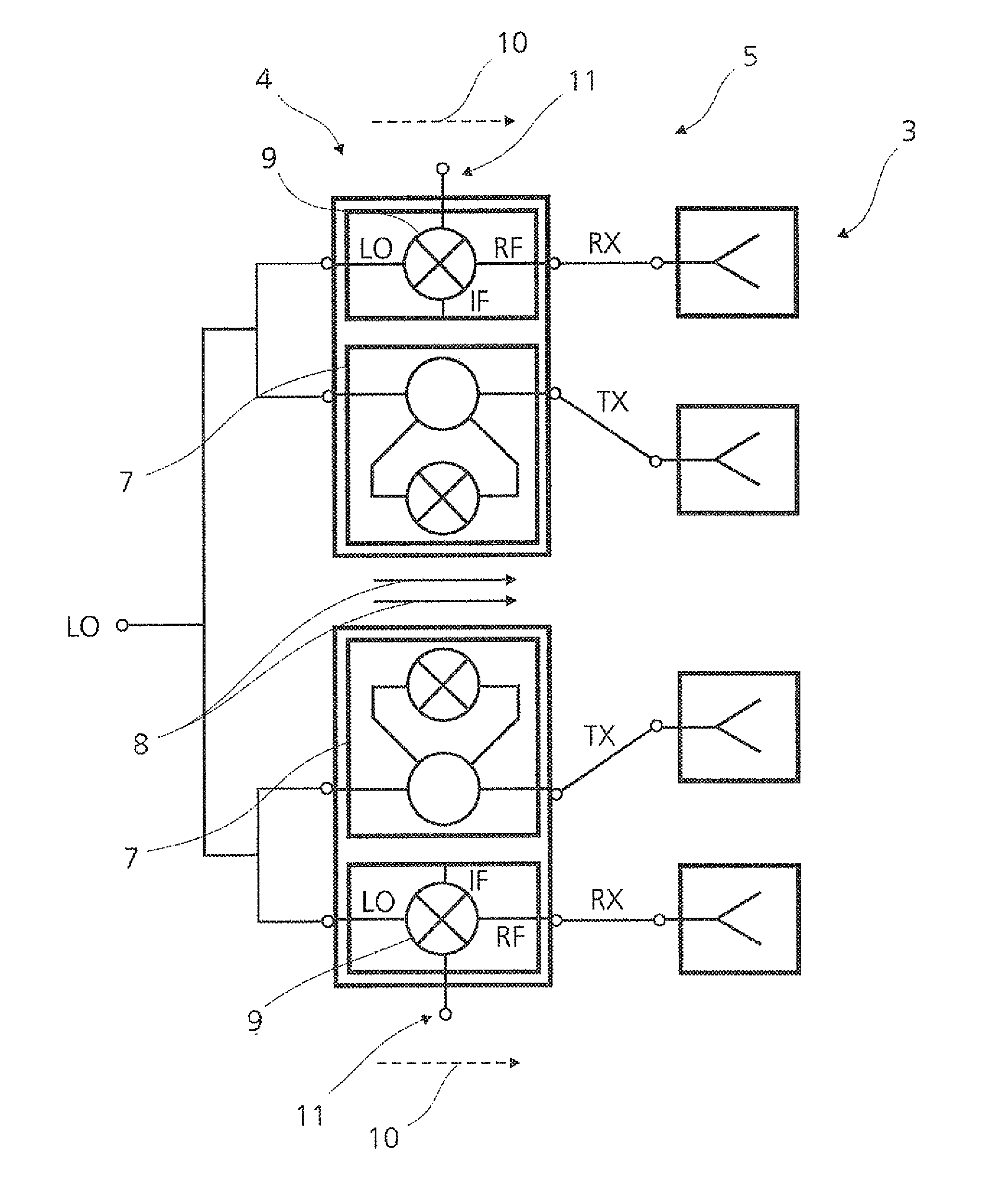
[0020]FIG. 2 shows receiver architecture 5 in greater detail, including antenna unit 3 and mixer system 4. A local oscillator signal LO is supplied via an input or a local oscillator supply. Transfer mixer units or tr...


PUM


Abstract

A monostatic multibeam radar sensor device for a motor vehicle, including a directional characteristic of an antenna unit having at least one transceiving channel and at least one receiving channel, and including a mixer system, which has an at least approximately isolating mixer for at least one of the receiving channels. The at least approximately isolating mixer includes a Gilbert cell mixer, which, due to a non-ideal isolation between an input of the local oscillator signal and the corresponding receiving channel, emits a transmission power via this receiving channel, using an overcoupling signal, the transmission power influencing the directional characteristic of the antenna unit and the directional characteristic being switchable by controlling the phase position of the overcoupling signal.

Description

FIELD OF THE INVENTION[0001]The present invention relates to a monostatic multibeam radar sensor device for a motor vehicle, including a directional characteristic of an antenna unit having at least one transceiving channel and at least one receiving channel, and including a mixer system, which has an at least approximately isolating mixer for at least one of the receiving channels. The present invention also relates to a Gilbert cell mixer for a monostatic multibeam radar sensor device of this type, as well as to a method for operating a monostatic multibeam radar sensor device of this type.BACKGROUND INFORMATION[0002]Radar sensors of this type are used, for example, in distance warning and regulating systems in motor vehicles, in particular adaptive cruise control (ACC) systems. Adaptive cruise control systems of this type are described in the publication by Robert Bosch GmbH, “Adaptive Fahrgeschwindigkeitsregelung ACC” (ACC Adaptive Cruise Control), Yellow Series, 2002 edition, T...

Claims


Application Information

Patent Timeline
Patent Type & Authority Patents(United States)
IPC IPC(8): G01S13/48H01Q3/12G01S13/931
CPCG01S7/036G01S7/35G01S13/931G01S13/48G01S2013/9325
Inventor BINZER, THOMASHAUK, JOACHIMSTEINBUCH, DIRK
Owner ROBERT BOSCH GMBH
Why Eureka
Try Eureka