Medical implantable lead and method for the manufacture thereof

a technology of implantable lead and lead plate, which is applied in the direction of external electrodes, sensors, diagnostics, etc., can solve the problems of increased rigidity, increased thickness of implantable lead, and increased contact temperature of electrodes, so as to increase the pitch of helically wound wires and increase the angle

Inactive Publication Date: 2013-05-14
ST JUDE MEDICAL
View PDF9 Cites 3 Cited by
  • Summary
  • Abstract
  • Description
  • Claims
  • Application Information

AI Technical Summary

Benefits of technology

[0008]It is an object of the invention to provide a medical implantable lead having an improved shielding in relation to prior art. More specifically, it is an object to provide a shielded medical implantable lead, by which the shielding can be made with excellent shielding properties and in a cost-saving way.
[0011]Several advantages may be achieved by a medical implantable lead formed in this way. One advantage is that a wire coil having an electrical shielding according to the invention, may be manufactured to a cost that is not significantly higher than for manufacturing a regular coil without any shielding.
[0012]Another advantage is that the shielding properties for a wire coil according to the invention will be improved in relation to a regular shielding in form of a tube of braided wires. This is due to the fact that, since the coil is close-lapped and adjacent loops of the coil will normally be in contact with each other, the conducting path for the induced electric current in the shield layer will be directed in the longitudinal direction of the lead, while the conducting path for the signals in the wire core will be directed in the longitudinal direction of the wires, i.e. nearly 90° in relation to each other since the wire is close-lapped. Small spacings may sometimes be formed between adjacent loops when the lead is bent. However, the small capacitance occurring at the near lying shield layers, will act as a short for the high frequency signals such that electric contact and a conducting path in the longitudinal direction of the lead is nevertheless maintained. However, the possible electric current induced into the outer conducting shield layer, will in its turn have a low susceptibility of inducing its electric current into the wire core since their mutual direction of current flow, will have a large angle, of almost 90° in relation to each other. Moreover, any current induced from the electromagnetic field and from the current in the outer conducting shielding layer into the wire core of the coil will, since it usually concerns electromagnetic fields of very high frequencies, generally radio frequencies of about 30 MHz or more, experience a very high impedance in the coiled conductor which effectively will counteract any induced current in the wire coil. Also, the reactance between adjacent loops of the central wire core will be rather high due to the insulation layer around the wire core, such that the capacitive coupling between adjacent loops will be low which effectively will reduce any current flow due to capacitive coupling.
[0013]It is also an advantage that the present invention will result in a less increment of the diameter and the stiffness of the wire coil in comparison with using an ordinary shielding in form of a tube of braided wires, since the shield layer may be formed with a small thickness.
[0020]The angle between the axial direction of the lead, i.e. the direction which the induced current in the electrical conducting shield layer will have, and the direction of the inner wire core, i.e. the direction of the signals between the electrode and the monitoring and / or controlling device, is dependant of the outer diameter of the wire, the diameter of the wire coil and the number of wires in the wire coil. If, for example, the wire coil has two or more individual wires, the angle will be smaller than if the wire coil only comprises one single wire, since with two or more wires the pitch of the helically wound wires will increase. Generally, it is advantageous the larger the angle is and it is preferred that the angle is at least 70°.

Problems solved by technology

This induced current may cause heating in the electrode that is in contact with the tissue of the organ.
If the heating is too high, there is a risk that this will cause damage to the tissue.
However, such shielded medical implantable leads are associated with several disadvantages.
The braided shielding will give the medical implantable lead an increased thickness as well as increased rigidity, which normally is not desirable.
Moreover, the braided shielding will considerably increase the cost for manufacturing the lead, since it will involve the provision of one additional component, which has to be mounted when assembling the lead.
Also, it has appeared that such a braided shielding can not prevent the induction of electrical current to the coiled conductor in a degree that is sufficient to safely permit an individual, having an implanted lead to be exposed to a MRI scanning.

Method used


Image

  • Medical implantable lead and method for the manufacture thereof
  • Medical implantable lead and method for the manufacture thereof
  • Medical implantable lead and method for the manufacture thereof

Examples


Embodiment Construction

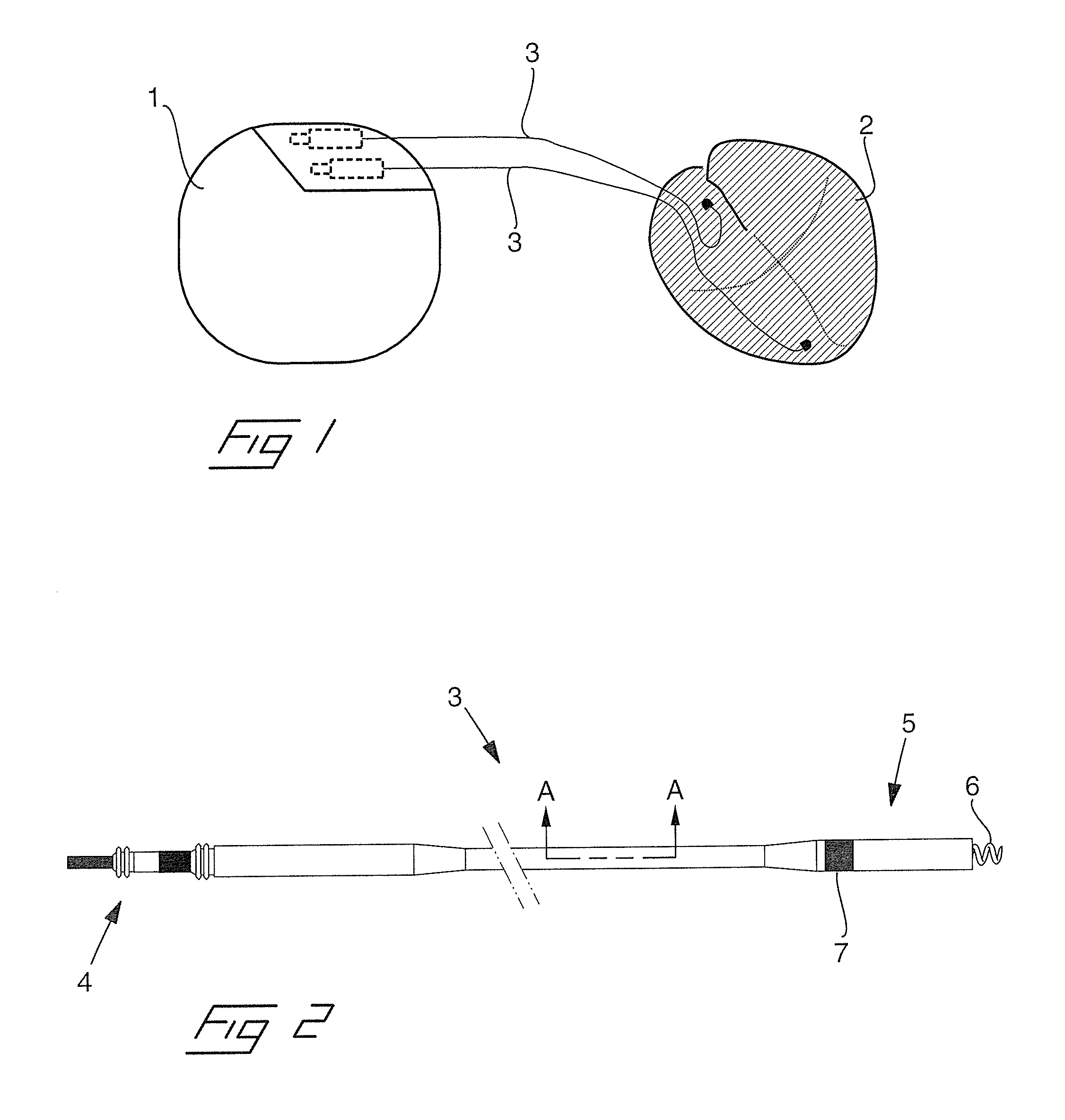
[0028]Reference is first made to FIG. 1, in which is shown, in a schematic view, the connection of a pacemaker 1 to a heart 2 by means of two medical implantable leads 3. More precisely, one lead is connected to the right atrium and the other lead is connected to the right ventricle of the heart for monitoring and pacing of the heart rate. The pacemaker is normally adapted to be implanted under the skin of the patient, e.g. in the area of one of the collar bones, and the leads can preferably be inserted through a vein leading to the heart. It is to be noted that the reproduction scale of the pacemaker and the heart in the view of FIG. 1 are different for simplified drawing.

[0029]In FIG. 2 is illustrated a medical implantable lead 3, which has been shortened for simplified drawing. The lead has a connector 4 in a proximal end for connection to the pacemaker, an intermediate flexible lead portion, and a so called header 5 in a distal end. The header is provided with a helix 6, which c...


PUM

PropertyMeasurementUnit
angleaaaaaaaaaa
thicknessaaaaaaaaaa
thicknessaaaaaaaaaa

Abstract

A medical implantable lead adapted to be implanted into a human or animal body for monitoring and / or controlling of an organ inside the body has a fixation in a distal end, which is adapted to fix a distal end of the lead to the organ, an electrode member in the distal end adapted to be in contact with tissue of the organ and receive and / or transmit electrical signals from and / or to the organ, and at least one electrically conducting coil, which includes one or more electrically conducting helical wires and that is adapted to connect the electrode member in the distal end with a monitoring and / or controlling device in a proximal end of the lead. One or more of the individual wires of the coil has a wire core that is provided with a surrounding electrically insulating layer, which in turn is provided with a surrounding electrically conducting shield layer, and the coil is close lapped such that electrically conducting shield layers of adjacent loops of the coil are in electrical contact with each other.

Description

BACKGROUND OF THE INVENTION[0001]1. Field of the Invention[0002]The present invention relates to a medical implantable lead of the type adapted to be implanted into a human or animal body for monitoring and / or controlling of an organ inside the body, having a fixation means in a distal end that is adapted to fix the distal end of the lead to the organ, an electrode member in the distal end adapted to be in contact with tissue of the organ and receive and / or transmit electrical signals from and / or to the organ, and at least one electrically conducting coil, which includes one or more electrically conducting helical wires and that is adapted to connect the electrode member in the distal end with a monitoring and / or controlling device in a proximal end of the lead.[0003]The invention also relates to a method for manufacturing of a medical implantable lead.[0004]2. Description of the Prior Art[0005]It is well known in the art to use a medical implantable lead of the above kind to monito...

Claims


Application Information

Patent Timeline
Patent Type & Authority Patents(United States)
IPC IPC(8): A61N1/05
CPCA61N1/05A61N1/056Y10T29/49002A61N2001/086A61N1/3718A61N1/086
Inventor STRANDBERG, HANSSIVARD, .ANG.KEBROOME, .ANG.SADAHLBERG, KENNETHPELLIJEFF, GUSTAVHENRIQUEZ, LEDA
Owner ST JUDE MEDICAL
Why Eureka
Try Eureka