Imaging lens unit

a technology of lens unit and image, applied in the field of image lens unit, can solve the problems of difficult to achieve both miniaturization and adequate aberration correction, and difficult to reduce costs, so as to achieve the effect of reducing costs and simplifying the manufacturing process

Active Publication Date: 2013-06-18
TOKYO VISIONARY OPTICS CO LTD
View PDF5 Cites 12 Cited by
  • Summary
  • Abstract
  • Description
  • Claims
  • Application Information

AI Technical Summary

Benefits of technology

[0011]The present invention has been made in view of the above circumstances and has an object to provide an imaging lens unit for a solid-state image sensor which features miniaturization, high performance and low cost.
[0013]In the above imaging lens unit, the first and second lenses are mainly responsible for generation of required power and correction of chromatic aberrations while the third to fifth lenses are primarily responsible for correction of astigmatism and field curvatures. Since the second lens has negative refractive power with its convex surface facing the object side near the optical axis, spherical aberrations can be corrected adequately; and since the third lens has negative refractive power with its convex surface facing the object side near the optical axis and its power is small, off-axis aberrations (coma aberrations and field curvatures in particular) are corrected adequately while least affecting the power of the whole system. Also, since the aperture stop is located on the object side of the first lens, control of CRA (Chief Ray Angle) is easy. In other words, for an image sensor which must be telecentric, the light ray incidence angle can be easily controlled and the required light intensity is obtained in a peripheral area where the light intensity tends to be low. By balancing the lens shape and lens refractive power optimally, a compact high-performance imaging lens unit is obtained.
[0017]The conditional expression (2) represents a condition required to define the shape of the third lens. In the present invention, the distance between the second and third lenses as well as the distance between the third and fourth lenses are minimized for miniaturization. Specifically, the basic curvature radius ratio of the object side surface of the third lens to its image side surface is set to around 1.0. Furthermore, the thickness difference between the center and peripheral area of the lens is decreased and variation in the aspheric sag amount of the object side surface and image side surface is minimized. If the ratio in the conditional expression (2) is above the upper limit “1.2” or below the lower limit “0.9”, undesirably the thickness unevenness increases and the cubic volume occupied by the third lens increases.
[0020]The conditional expression (4) represents a condition required to shorten the optical total length while keeping good optical performance. Since the negative power of the fifth lens is relatively large, a so-called telephoto capability is obtained, contributing to miniaturization. If the ratio in the conditional expression (4) is above the upper limit “−0.3”, the negative power of the fifth lens is too large (though it is advantageous in terms of reduction in total length) and the sensitivity to manufacturing errors becomes higher, which is disadvantageous in terms of stability in mass production. On the other hand, if the ratio is below the lower limit “−0.8”, the negative power of the fifth lens is too small and it is difficult to shorten the total length.
[0029]It is desirable that all the constituent lenses be made of a plastic material. If all the constituent lenses are made of a plastic material, the imaging lens unit can be mass-produced and its cost can be reduced. In the present invention, chromatic aberrations are mainly corrected by the second lens and the second lens is made of a material with a small Abbe number such as polycarbonate and the first, third, fourth, and fifth lenses are all made of a cycloolefin polymer plastic material. The manufacturing process is simplified by using the same plastic material as much as possible for the plastic lenses which constitute the imaging lens unit.

Problems solved by technology

For the imaging lens units described in Patent Documents 1 and 2, which use five lenses for performance enhancement, it is difficult to achieve both miniaturization and adequate aberration correction because the total lens system length is large.
In addition, since they use a glass material, it is not easy to reduce the cost.

Method used


Image

  • Imaging lens unit
  • Imaging lens unit
  • Imaging lens unit

Examples


embodiment 1

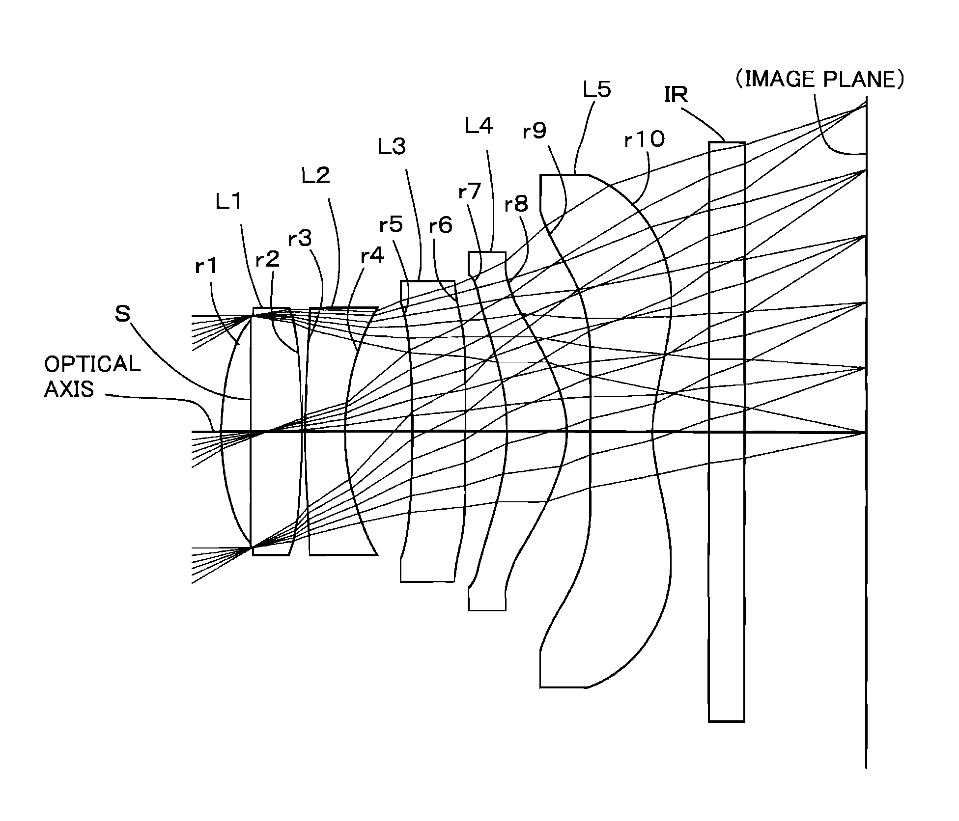
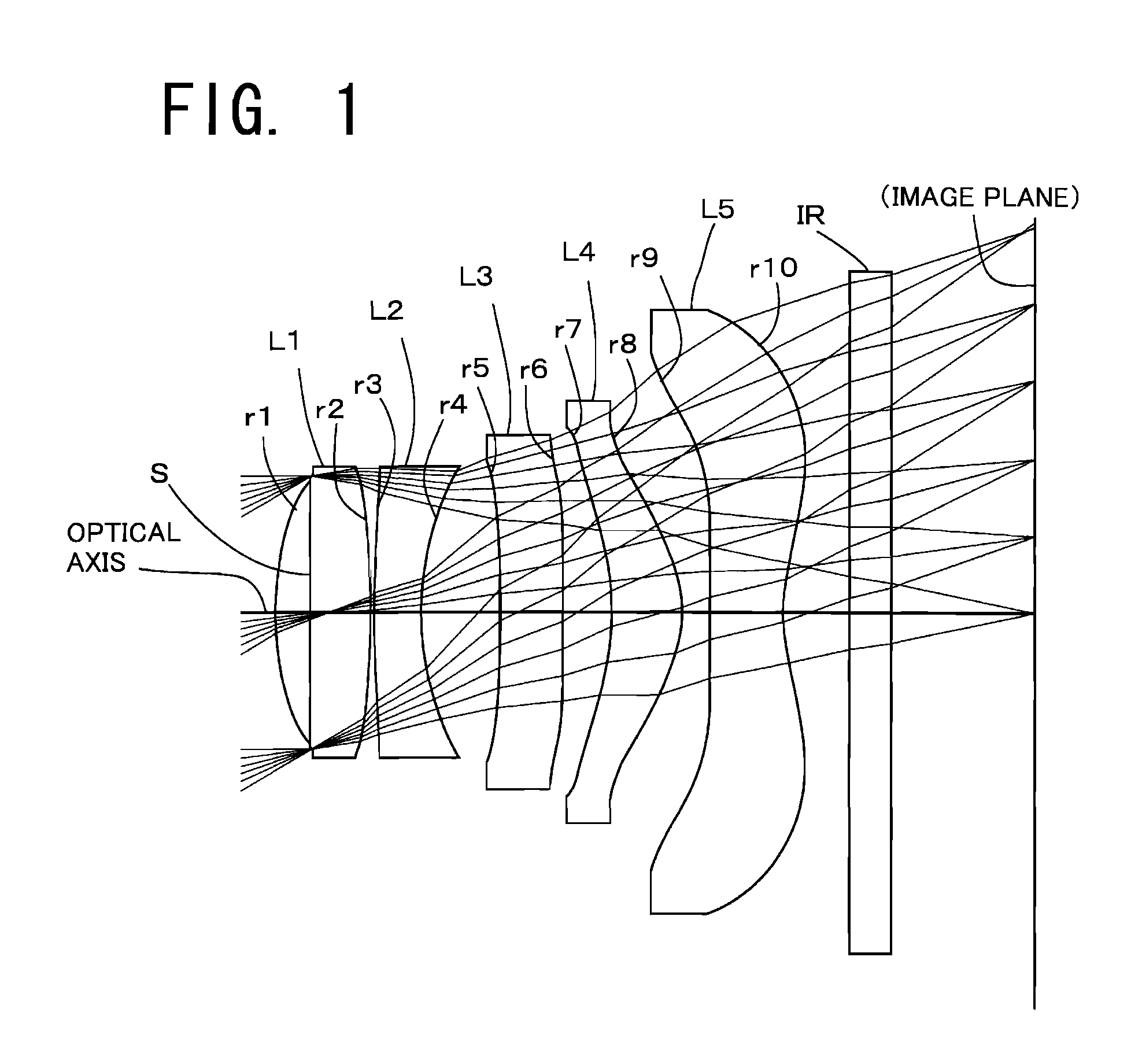
[0043]FIGS. 1 and 3 are sectional views of lenses according to Examples 1 and 2 of the first embodiment of the present invention. The basic lens structure is identical between the examples, so the structure of the imaging lens unit according to the first embodiment is explained below referring to the sectional view of the lens unit in Example 1.

[0044]As shown in FIG. 1, in the imaging lens unit according to the first embodiment, the constituent lenses are arranged from the object side to the image side in the following order: an aperture stop S, a first lens L1, second lens L2, a third lens L3, a fourth lens L4, and a fifth lens L5. A cover glass IR is placed between the fifth lens L5 and image plane. This cover glass is omissible. The first lens L1 is a biconvex lens with one convex surface facing the object side and the other facing the image side; the second lens L2 is a lens with negative refractive power lens having a convex surface facing the object side near the optical axis;...

example 1

[0059]Table 1 shows the basic lens data of the imaging lens unit in Example 1.

[0060]

TABLE 1f = 4.8341    Fno = 2.405    ω = 30.463°iRdNdνdS (aperture stop)∞−0.2451*1.9200.6981.53556.22*−4.9890.0233*11.3160.3481.61425.64*1.9500.5825*56.9790.4681.53556.26*51.7980.367*−1.9840.5181.53556.28*−0.9970.20459*12.7830.54281.53556.210* 1.4660.511 ∞0.31.51764.212 ∞1.047IMA∞ikA4A6A8A10A12A141*−8.984E−011.386E−02−4.452E−03−3.635E−036.925E−04−8.637E−04−5.237E−032*−9.222E+01−2.778E−031.138E−02−2.995E−02−1.127E−024.241E−032.486E−033*2.370E+01−2.865E−026.387E−02−5.835E−024.217E−03−2.627E−031.038E−024*−3.288E−01−1.219E−011.557E−01−9.759E−023.109E−02−6.668E−036.555E−035*0.000E+00−1.085E−012.088E−032.471E−026*0.000E+00−8.922E−025.635E−02−4.296E−021.935E−02−2.144E−037*8.968E−014.373E−028.519E−02−5.000E−021.419E−02−7.279E−048*−2.541E+00−1.130E−02−9.215E−042.091E−02−3.309E−03−6.569E−049*2.998E+01−7.461E−02−5.870E−033.201E−035.679E−04−2.374E−05−2.461E−0510* −9.099E+00−7.716E−022.012E−02−5.983E−031.079E−03−9...

example 2

EXAMPLE 2

[0072]Table 2 shows the basic lens data of the imaging lens unit in Example 2.

[0073]

TABLE 2f = 4.82595    Fno = 2.400    ω = 30.484°iRdNdνdS (aperture stop)∞−0.251*1.9200.6791.53556.22*−5.1000.0233*9.0650.36051.61425.64*1.8530.5925*51.0000.4391.53556.26*50.0000.3757*−1.9150.5181.53556.28*−0.9880.1919*9.6790.53081.53556.210* 1.4640.511 ∞0.31.51764.212 ∞1.081IMA∞ikA4A6A8A10A12A141*0.000E+00−1.841E−03−1.651E−021.820E−02−1.883E−022*−8.187E+012.887E−034.435E−03−2.313E−023*2.334E+00−3.108E−026.707E−02−5.101E−021.538E−02−5.459E−034.460E−034*0.000E+00−1.341E−011.587E−01−1.056E−014.540E−02−4.181E−03−8.490E−045*0.000E+00−1.226E−015.463E−032.911E−026*0.000E+00−9.733E−023.206E−021.364E−037*8.240E−013.519E−029.267E−02−4.094E−028.895E−038*−2.462E+00−7.565E−033.357E−032.084E−02−5.920E−039*1.627E+01−6.498E−02−7.256E−032.663E−035.157E−04−1.164E−05−2.080E−0510* −9.192E+00−7.339E−021.842E−02−5.591E−031.022E−03−8.684E−05f3 = −5609.97f5 = −3.2876f12 = 5.782f345 = 25.731EPD = 2.01

[0074]The valu...


PUM


Abstract

A compact low-cost imaging lens unit for a solid-state image sensor which corrects various aberrations adequately and produces a high-resolution high-definition image. The components of the unit are arranged from an object side to an image side in the following order: an aperture stop, a first lens with positive refractive power having a convex surface facing the object side, a second lens with negative refractive power having a convex surface facing the object side near an optical axis, a third lens with negative refractive power having a convex surface facing the object side near the optical axis, a fourth lens as a meniscus lens with positive refractive power having a convex surface facing the image side near the optical axis; and a fifth lens with negative refractive power having a concave surface facing the image side near the optical axis.

Description

[0001]The present application is based on and claims priority of Japanese patent application No. 2011-041734 filed on Feb. 28, 2011, the entire contents of which are hereby incorporated by reference.BACKGROUND OF THE INVENTION[0002]1. Field of the Invention[0003]The present invention relates to imaging lens units for solid-state image sensors which are used in small imaging devices used in small low-profile electronic devices such as mobile terminals including mobile phones and hand-held games and PDAs (Personal Digital Assistance).[0004]2. Description of the Related Art[0005]With the recent expansion of the market for mobile terminals with imaging devices, the use of a high-resolution small solid-state image sensor in an imaging device has been spreading.[0006]With the growing tendency for smaller and higher resolution image sensors, imaging lens units are required to provide higher performance in terms of resolution and image quality. Also, with the spread of such lens units, ther...

Claims


Application Information

Patent Timeline
Patent Type & Authority Patents(United States)
IPC IPC(8): G02B3/02G02B13/18G02B9/60
CPCG02B13/0045G02B1/041
Inventor YONEZAWA, TOMOHIROHASHIMOTO, MASAYA
Owner TOKYO VISIONARY OPTICS CO LTD
Why Eureka
Try Eureka