Heat exchanger system

a technology of heat exchanger and filter head, which is applied in the direction of heating of turbine/propulsion fuel, separation process, lighting and heating apparatus, etc., can solve the problem of increasing the head loss of the filter

Active Publication Date: 2013-06-25
SN DETUDE & DE CONSTR DE MOTEURS DAVIATION S N E C M A
View PDF53 Cites 4 Cited by
  • Summary
  • Abstract
  • Description
  • Claims
  • Application Information

AI Technical Summary

Benefits of technology

[0011]The aim of the invention is to propose a heat exchanger system that makes it possible to use, if desired, a heat

Problems solved by technology

This accumulation of impurities causes fouling of the filte

Method used


Image

  • Heat exchanger system
  • Heat exchanger system

Examples


Embodiment Construction

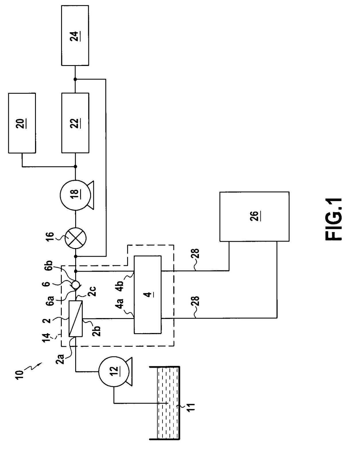
[0022]FIG. 1 diagrammatically illustrates an example of a fuel circuit 10 for an airplane jet engine.

[0023]Upstream and downstream are defined in this application in relation to the normal direction of flow of the liquid (here the fuel) passing through the circuit and the system of the invention.

[0024]The circuit 10 comprises, from upstream to downstream: a fuel tank 11 (this is the airplane fuel tank); a low-pressure pump 12 pumping the fuel into said tank 11; a heat exchanger system 14 according to the invention, supplied by the pump 12; a main filter 16; a high-pressure pump 18; a servo-control mechanism 20, supplied with fuel by the pump 18; a fuel regulator 22 supplied by the pump 18, and fuel injectors 24 situated downstream from the regulator 22. These injectors 24 are situated in the combustion chamber of the jet engine.

[0025]FIG. 1 also illustrates the oil circuit 28 making it possible to ensure the lubrication of the electricity generator, or IDG 26 of the airplane. The he...


PUM

PropertyMeasurementUnit
Lengthaaaaaaaaaa
Lengthaaaaaaaaaa
Pressureaaaaaaaaaa

Abstract

A heat exchanger system through which a liquid can flow, including a heat exchanger including a liquid inlet and a liquid outlet, a bypass valve including a liquid inlet and a liquid outlet, and a self-cleaning filter including a liquid inlet and two liquid outlets, one being an outlet for filtered liquid and one being an outlet for non-filtered liquid. The outlet for filtered liquid is connected to the inlet of the exchanger and the outlet for non-filtered liquid is connected to the inlet of the valve. The outlet of the heat exchanger is connected downstream of the outlet of the valve. A fuel circuit of an airplane jet engine can include such a system.

Description

FIELD OF THE INVENTION[0001]The invention concerns a heat exchanger system through which a liquid is intended to flow. Such a system can be mounted in any liquid (i.e. hydraulic) circuit, and in particular a fuel circuit or an oil circuit.[0002]This system can be used, for example, in a fuel circuit of a land or aeronautic turbomachine (jet engine or turbo-prop) and, more particularly, in a fuel circuit of an airplane jet engine.BACKGROUND OF THE INVENTION[0003]The invention concerns a heat exchanger system through which a liquid is intended to flow, the heat exchanger system being of the type comprising a heat exchanger with a liquid inlet and a liquid outlet. In operation, this heat exchanger is passed through, on one hand, by fuel coming from the airplane's tank, this fuel passing through said liquid inlet and outlet, and, on the other hand, by the oil from the lubrication circuit of the airplane's integrated drive generator (IDG), this oil passing through other liquid inlets and...

Claims


Application Information

Patent Timeline
IPC IPC(8): B01D35/147
CPCF02C7/224F28F27/02F28F19/01Y02T50/671Y02T50/60
Inventor BRUN, GILLES
Owner SN DETUDE & DE CONSTR DE MOTEURS DAVIATION S N E C M A
Why Eureka
Try Eureka