Lubricating system for air-cooled general-purpose engine

a general-purpose engine and lubricating system technology, applied in the direction of auxillary lubrication, piston pump, muscle-operated starters, etc., can solve the problems of difficult to cool an oil for lubricating components of general-purpose engines, harsh operation environment,

Active Publication Date: 2013-07-02
HONDA MOTOR CO LTD
View PDF10 Cites 0 Cited by
  • Summary
  • Abstract
  • Description
  • Claims
  • Application Information

AI Technical Summary

Benefits of technology

[0009]According to the first feature of the present invention, the oil discharged from the oil pump is jetted from the jet to the valve operating chamber through the oil-supply path. The oil thus jetted turns into mist, and thus allows preferable lubrication of components of intake and exhaust valves and of a valve operating system in the valve operating chamber.
[0010]Furthermore, the oil-supply path is formed in the one end wall, facing the cooling-air path, of the engine main body. Accordingly, the oil-supply path together with the one end wall is effectively cooled by the cooling air blown under pressure from the cooling fan. Thus, an oil whose temperature is increased during the operation of the general-purpose engine is also cooled, while passing through the oil-supply path. Thereby, together with the effect of pressure drop by jetting the oil from the jet, it is possible to form oil mist at an appropriate temperature in the valve operating chamber. Moreover, not only the lubrication of the intake and exhaust valves and the valve operating system but also effective cooling of these components is achieved.
[0012]According to the second feature of the present invention, the oil-supply path and the oil return path are formed in different regions of the engine main body; the one end wall and the other end wall, respectively. This makes it possible to prevent the formation of the oil-supply path and the oil return path from reducing the strengths of the one end wall and the other end wall as much as possible.

Problems solved by technology

Meanwhile, an air-cooled general-purpose engine is often operated in a stationary state as in, for example, a power source of an electric generator or the like, and the operation environment is harsh.
This makes it difficult to cool an oil for lubricating components of the general-purpose engine, particularly to cool an oil for lubricating a valve operating system that is far away from an oil reservoir in a bottom portion of a crankcase.

Method used


Image

  • Lubricating system for air-cooled general-purpose engine
  • Lubricating system for air-cooled general-purpose engine
  • Lubricating system for air-cooled general-purpose engine

Examples


Embodiment Construction

[0019]An embodiment of the present invention will be explained below based on FIG. 1 to FIG. 4.

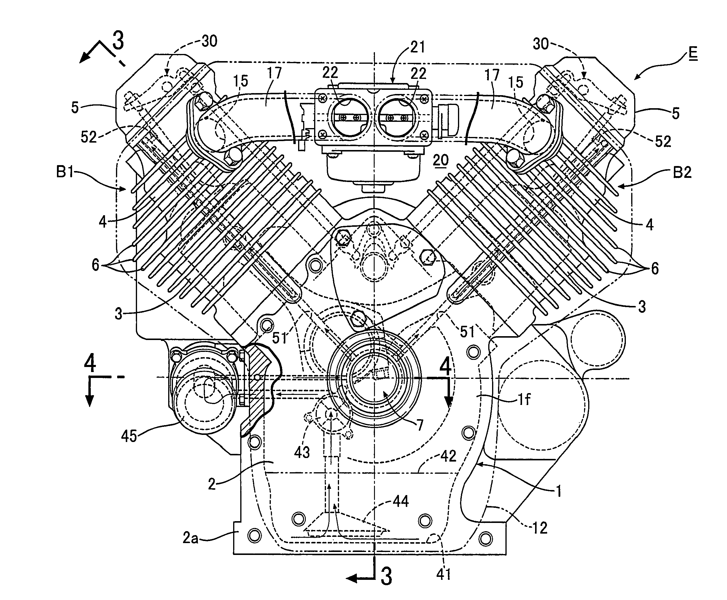
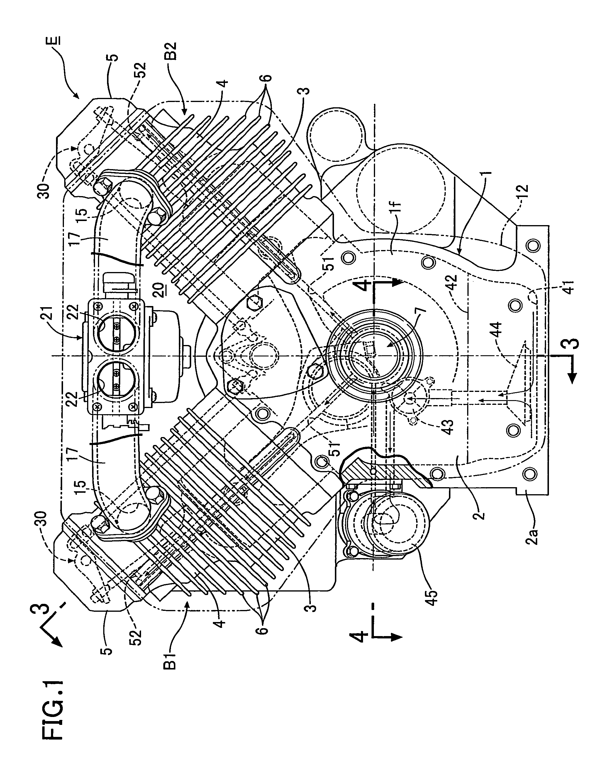
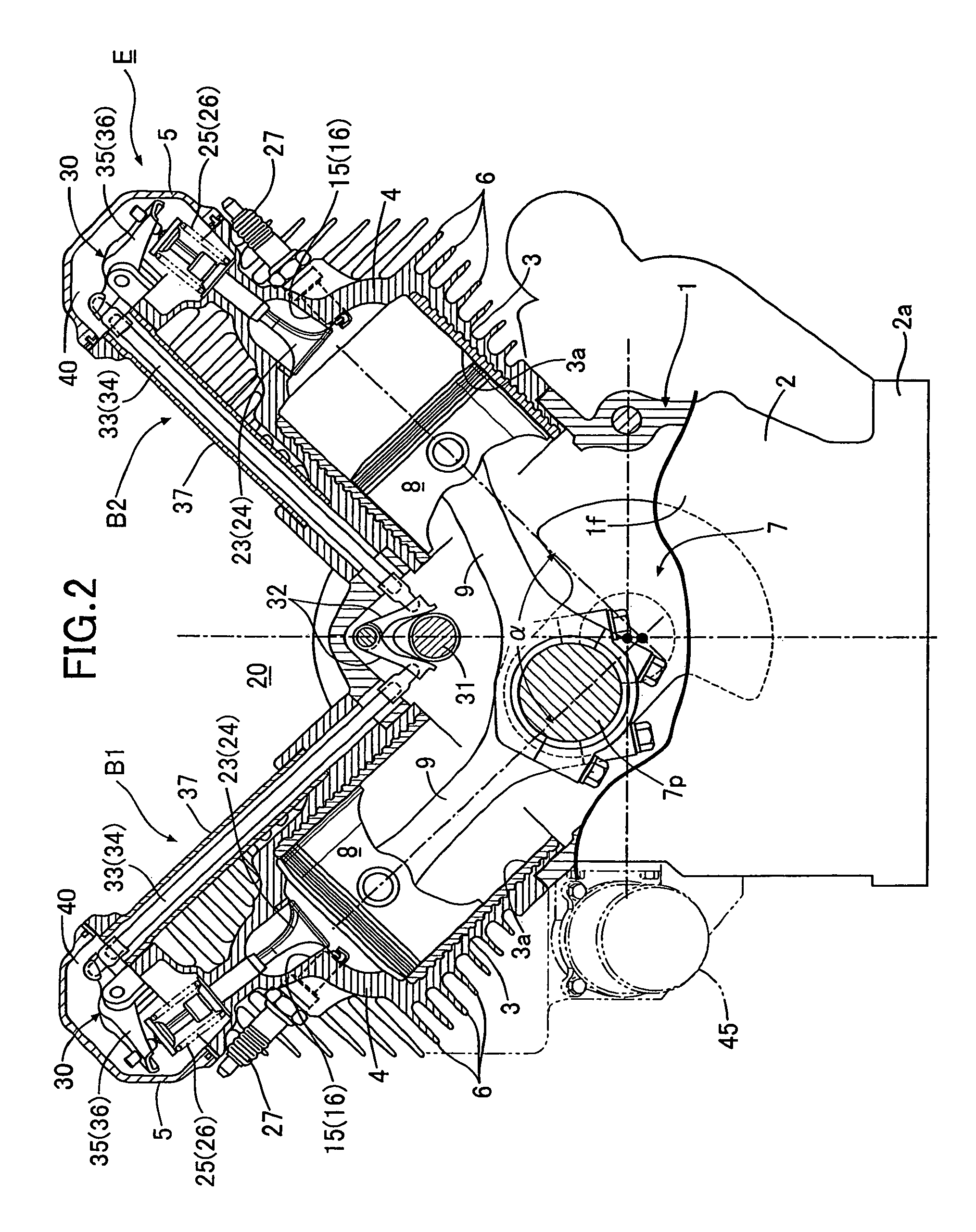
[0020]Firstly, in FIGS. 1 and 2, an engine body 1 of an air-cooled general-purpose V-type general-purpose engine includes: a crankcase 2; a first bank B1 and a second bank B2 which are arranged respectively on the left and right sides in a V-shape, and which are connected to an upper portion of the crankcase 2. An installation flange 2a is formed in a bottom portion of the crankcase 2. The first and second banks B1 and B2 are arranged in such a manner that the included angle α between the banks B1 and B2 is set at 90°.

[0021]Each of the first and second banks B1 and B2 includes: a cylinder block 3 which has a cylinder bore 3a, and which is bolt-coupled to the crankcase 2; and a cylinder head 4 which has a combustion chamber 4a leading to the cylinder bore 3a, and which is integrally connected to the cylinder block 3. A head cover 5 is bolt-coupled to an end surface of the cylinder head 4. E...


PUM


Abstract

An air-cooled general-purpose engine includes: a cooling fan fixed to one end portion, protruding outward from one end wall of an engine main body, of a crankshaft; and a shroud which is mounted to the engine main body, and which defines a cooling-air path between the shroud and the one end wall, the cooling-air path guiding a cooling air blown under pressure from the cooling fan. The air-cooled general-purpose engine includes: an oil pump which pumps up an oil from an oil reservoir; and an oil-supply path which is formed in the one end wall, facing the cooling-air path, of the engine main body, and configured to guide the oil discharged from the oil pump to a valve operating chamber in a head portion of the engine main body, and a jet for jetting the oil is provided in an opening of the oil-supply path, the opening being open to the valve operating chamber. Accordingly, it is possible to be excellent in cooling oil and to preferably lubricate a valve operating system in addition to the surrounding of a crankshaft.

Description

CROSS-REFERENCE TO RELATED APPLICATIONS[0001]The present invention claims priority under 35 USC §119 based on Japanese patent application No. 2008-149707 filed Jun. 6, 2008. The subject matter of this priority document is incorporated by reference herein.BACKGROUND OF THE INVENTION[0002]1. Field of the Invention[0003]The present invention relates to an air-cooled general-purpose engine comprising: a cooling fan fixed to one end portion of a crankshaft supported by an engine main body, the one end portion protruding outward from one end wall of the engine main body; and a shroud which is mounted to the engine main body, and which defines a cooling-air path between the shroud and the one end wall, the cooling-air path guiding a cooling air blown under pressure from the cooling fan, and especially relates to an improvement of a lubricating system for said engine.[0004]2. Description of the Related Art[0005]Conventionally, as a lubricating system for a general-purpose engine, a force-fe...

Claims


Application Information

Patent Timeline
Patent Type & Authority Patents(United States)
IPC IPC(8): F02B67/00F02B41/00F02B77/04F02F7/00F02N1/00F16M1/00F02M25/00F02M35/02F01M1/06F02B75/22F02F1/10
CPCF01M1/08F01M5/002F01M9/10F01M11/02
Inventor OGAWA, KAZUHISAHASEBE, HIROAKI
Owner HONDA MOTOR CO LTD
Why Eureka
Try Eureka