Vehicle heat management device

a technology for heat management devices and vehicles, which is applied in the direction of machines/engines, engine starters, transportation and packaging, etc., can solve the problems of affecting the operation of the vehicle, the valve is not operable, and the output of the engine cannot be controlled, so as to achieve the desired operating performance of the vehicle more quickly, improve visibility, and secure the effect of the vehicle's drivability

Active Publication Date: 2013-07-02
TOYOTA JIDOSHA KK
View PDF9 Cites 1 Cited by
  • Summary
  • Abstract
  • Description
  • Claims
  • Application Information

AI Technical Summary

Benefits of technology

[0008]Accordingly, in the present invention, heat produced by the heat source mounted in the vehicle is supplied first to the valve warm-up portion that warms up the intake air amount regulating valve and then to the transmission warm-up portion that warms up the transmission, after the engine is started. This rapidly defrosts the intake air amount regulating valve even when there is an extremely low ambient temperature, thus ensuring desired operating performance of the vehicle more quickly. As a result, according to the present invention, the heat management in the vehicle when there is an extremely low ambient temperature is performed in a desired manner.
[0009]If the vehicle includes a heater core for heating the passenger compartment as a component that receives heat from the heat source, it is desirable to configure the control section to control the heat supply from the heat source in such a manner as to supply heat to the heater core preferentially over the transmission warm-up portion. Specifically, when at an extremely low ambient temperature, frost may form in a window of the vehicle and thus deteriorate visibility for the driver, making it difficult to drive the vehicle. Such window frost formation may be stopped by blowing warm air from a heater onto the glass of the window. For this purpose, it is necessary to ensure desired heater performance. In this regard, by supplying heat to the heater core preferentially over the transmission warm-up portion, the desired heater performance is ensured at an earlier stage, and drivability of the vehicle is secured more quickly.
[0010]If the heater core for heating the passenger compartment is provided as a component that receives heat from the heat source, it is more desirable to configure the control section to control the heat supply from the heat source in such a manner that heat supply to the valve warm-up portion and the heater core, heat supply to the heater core, and heat supply to the valve warm-up portion and the transmission warm-up portion are performed sequentially in this order after starting of the engine. Specifically, in this case, heat is supplied first to the valve warm-up portion and the heater core after the engine is started, thus defrosting the intake air regulating valve or the window. This ensures drivability and desired operating performance of the vehicle. Subsequently, the heat supply to the heater core is carried out to heat the passenger compartment, thus ensuring comfort for the passengers. Finally, the heat is supplied to the valve warm-up portion and the transmission warm-up portion to ensure desired fuel economy performance of the vehicle. Through such heat supply to the components of the vehicle, heat management when there is an extremely low ambient temperature is performed in a desired manner.
[0011]It is preferred for the heat management device to start the heat supply to the transmission warm-up portion on condition that the portion that has received heat preferentially over the transmission warm-up portion, which are the intake air amount regulating valve or the heater device for the passenger compartment (or the passenger compartment), is completely warmed-up. In this manner, heat is supplied preferentially to the valve warm-up portion or the heater core until the intake air amount regulating valve and the window of the vehicle are defrosted. This ensures desired operating performance and drivability of the vehicle more quickly and reliably.

Problems solved by technology

At an extremely low ambient temperature, frost may form in intake air amount regulating valves of an engine, such as a throttle valve or an exhaust gas recirculation (EGR) valve, immediately after engine starting, thus causing operational failure of the valve.
In this case, output of the engine cannot be regulated and thus operation of the vehicle is hampered.

Method used


Image

  • Vehicle heat management device
  • Vehicle heat management device
  • Vehicle heat management device

Examples


first embodiment

(First Embodiment)

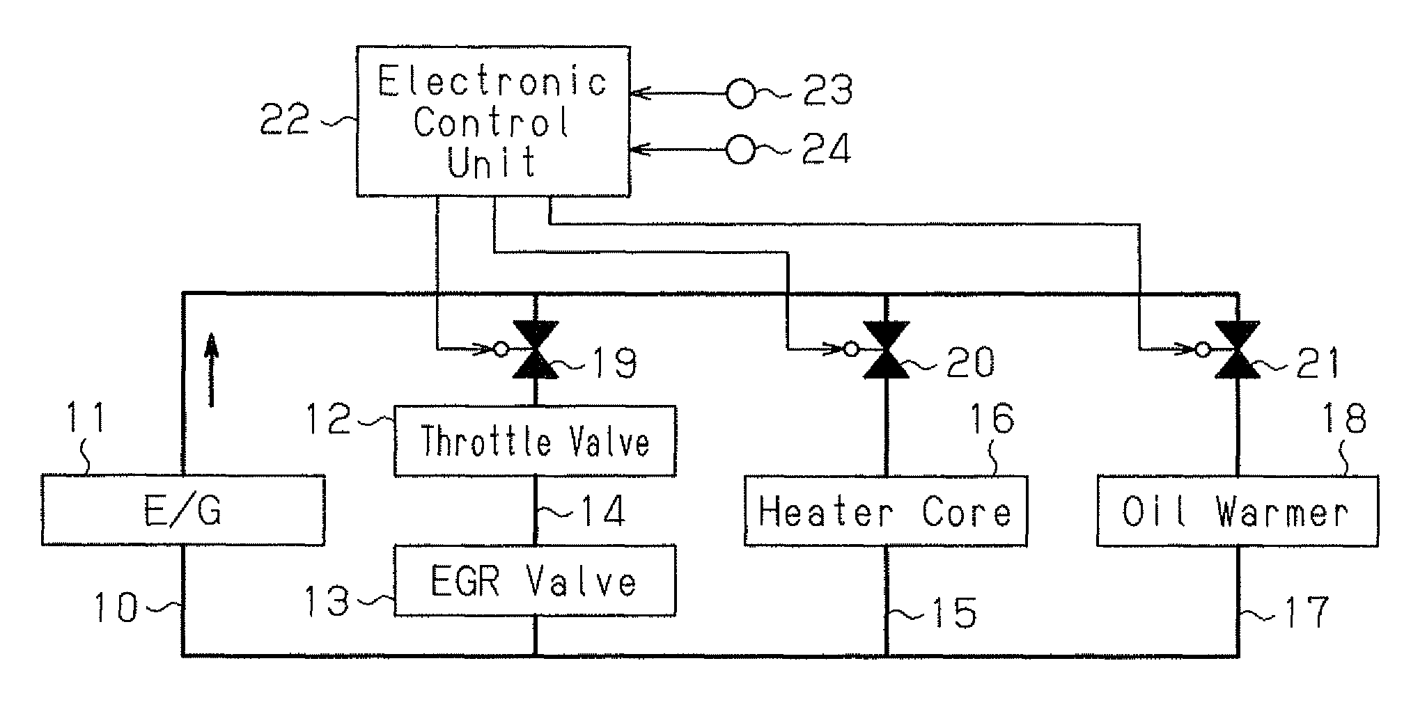
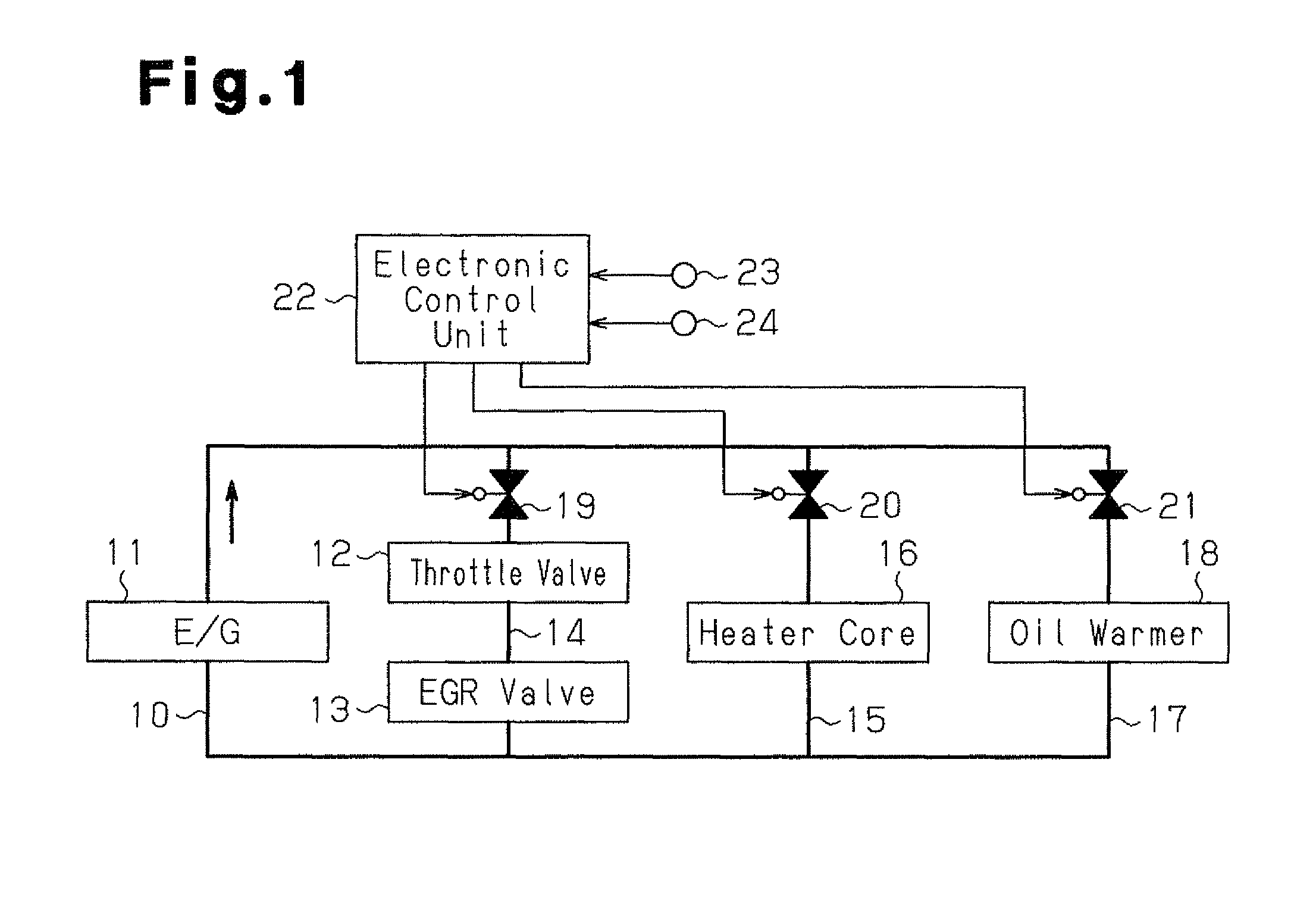
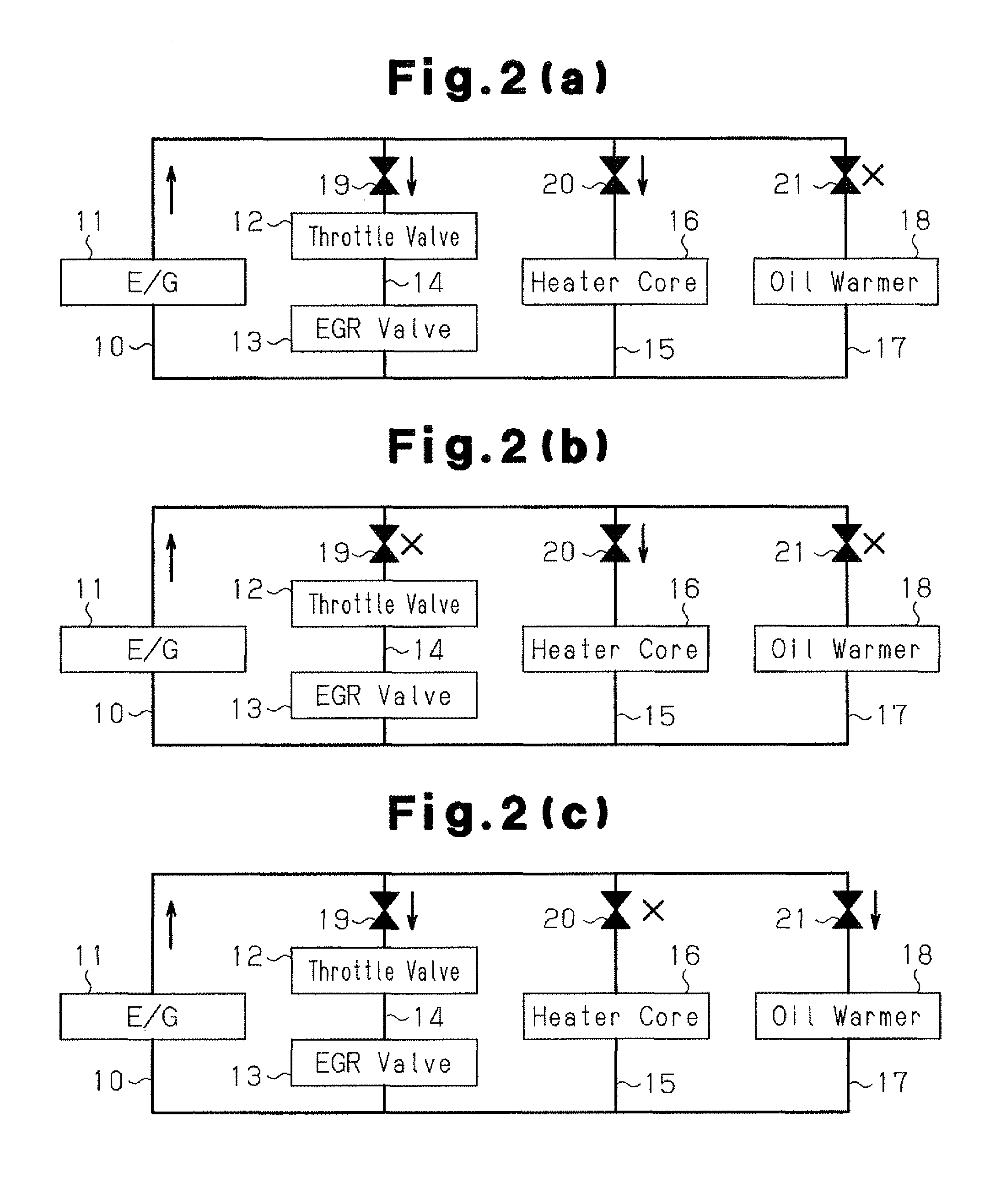
[0019]A first embodiment of a heat management device for a vehicle according to the present invention will now be described with reference to FIGS. 1 to 3. The heat management device for a vehicle of the first embodiment controls heat supply from an engine using engine coolant water as heat transfer medium to components of the vehicle. In the first embodiment, the engine corresponds to the heat source mounted in the vehicle.

[0020]The configuration of the heat management device for a vehicle of the first embodiment will hereafter be described with reference to FIG. 1. The vehicle in which the first embodiment is employed includes a coolant circuit 10 for circulating coolant water after the coolant water is heated by an engine 11 serving as the heat source. The coolant circuit 10 is divided into three coolant paths, which are a valve coolant path 14, a heater coolant path 15, and a warmer coolant path 17, at positions downstream of the engine 11.

[0021]The valve coola...

second embodiment

(Second Embodiment)

[0042]A second embodiment of the heat management device for a vehicle according to the present invention will hereafter be described with reference to FIGS. 4 and 5, mainly on the differences between the second embodiment and the first embodiment.

[0043]With reference to FIG. 4, the configuration of the heat management device for a vehicle of the second embodiment will be described. The vehicle in which the second embodiment is employed includes a coolant circuit 30 in which coolant water flows. The coolant circuit 30 extends through an engine 31, a throttle valve 32 and an EGR valve 33 both serving as an intake air amount regulating valve, and a heater core 34 for heating the passenger compartment. As a result, by supplying heat to the coolant circuit 30, the heat is supplied to the throttle valve 32 and the EGR valve 33, which are the intake air amount regulating valves. In the second embodiment, the coolant circuit 30 corresponds to the valve warm-up portion.

[00...


PUM


Abstract

When there is an extremely low ambient temperature, an electronic control unit controls operation of a circulation path for coolant water in such a manner that, after starting of an engine, the coolant water is supplied from the engine first to a throttle valve and an EGR valve and then to an oil warmer for a transmission. This solves a failure problem in the throttle valve and the EGR valve caused by frost formation at an early stage. As a result, desired operating performance of the vehicle is quickly ensured and heat management in the vehicle is carried out in a desired manner when there is an extremely low ambient temperature.

Description

FIELD OF THE INVENTION[0001]The present invention relates to a heat management device for a vehicle that controls heat supply from a heat source mounted in the vehicle to various components of the vehicle.BACKGROUND OF THE INVENTION[0002]To improve fuel economy performance and emission performance in a vehicle, precise heat management has been demanded in the vehicle as a whole. Conventionally, a device described in Patent Document 1 has been known as a heat management device for a vehicle. The heat management device activates various auxiliary heat sources in accordance with conditions for control of cooling of the power train or the battery and drive force and ensures air conditioning performance for the passenger compartment.[0003]Passenger comfort and fuel economy performance of a vehicle are considerations for heat management performed by the conventional heat management device. However, heat management for a particular condition such as an extremely low ambient temperature has...

Claims


Application Information

Patent Timeline
Patent Type & Authority Patents(United States)
IPC IPC(8): F16H59/00
CPCB60H1/00314B60H1/08F02B29/0493F02M25/0738F02N19/04F01P2060/16Y10T477/653F16H57/0413Y02T10/121Y02T10/146Y02T10/16F02M26/33Y02T10/12
Inventor ISHIKAWA, MASAHIDEUZUKI, KANAMEMORITA, ATSUSHITANAKA, KEIKOMIYAMOTO, YUKISHIGA, SATORUMORITA, MASAKIMATSUDA, MIYUKIORIHASHI, MANABUSAEKI, YOSHIHIROUNO, KEIICHINISHIMURA, HIROKIKUMAMOTO, TAKAYUKI
Owner TOYOTA JIDOSHA KK
Why Eureka
Try Eureka