Radiographic data interpretation

Active Publication Date: 2013-07-02
KROMEK
View PDF14 Cites 4 Cited by
  • Summary
  • Abstract
  • Description
  • Claims
  • Application Information

AI Technical Summary

Benefits of technology

[0041]The method and apparatus of the invention thus produces an output dataset with enhanced flexibility in regard to any such imaging.
[0042]Moreover, the advantage is not merely in the ability to re

Problems solved by technology

However most detector types are unable to resolve this energy information.
A limitation of using stereo pairs is that there is a v

Method used


Image

  • Radiographic data interpretation
  • Radiographic data interpretation
  • Radiographic data interpretation

Examples


Example

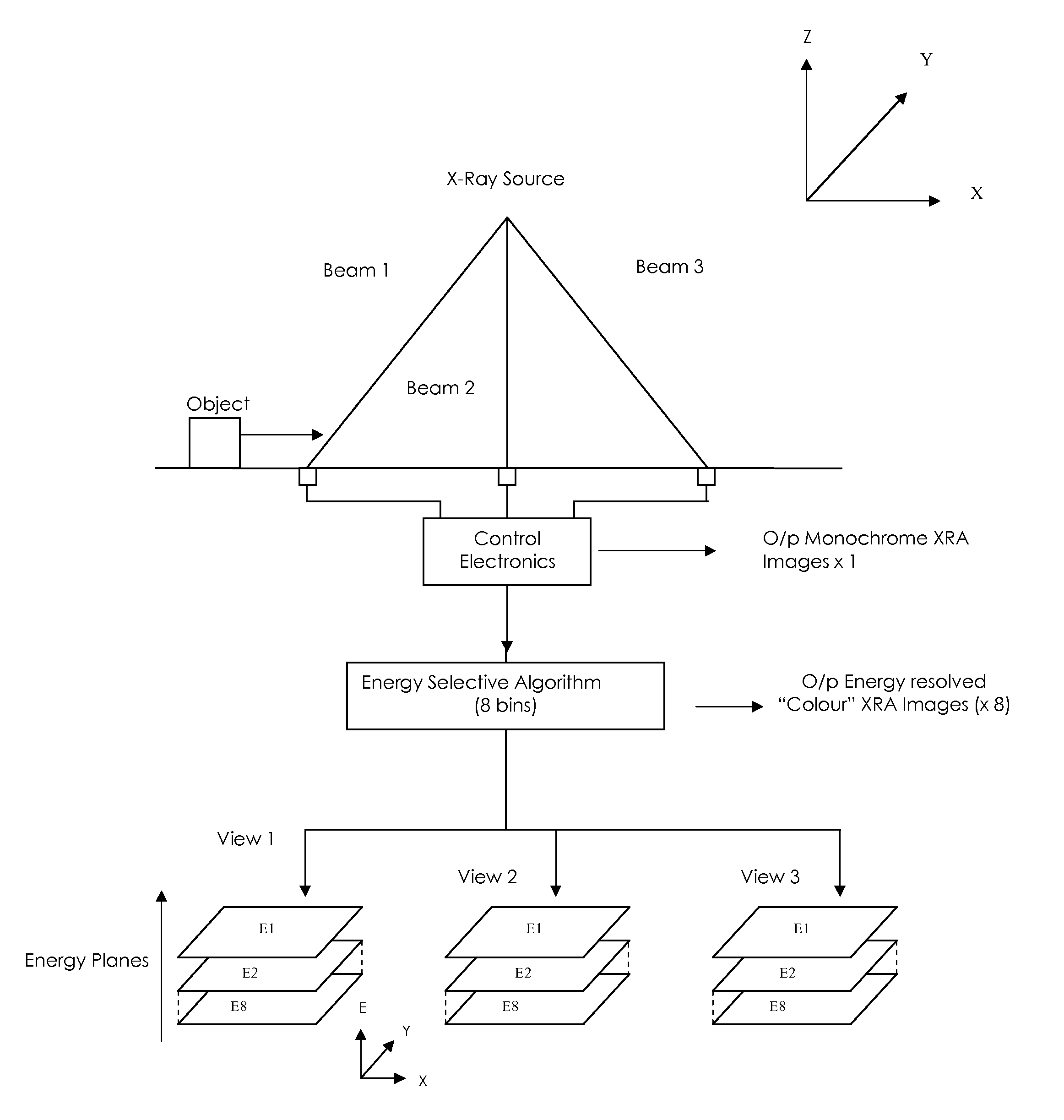
[0084]FIG. 1 presents in schematic manner both the apparatus for and the process of collection of transmission data from an object and the initial stages of processing that data in accordance with an embodiment of the invention for illustrative purposes. Apparatus features are presented schematically, and represented in spaced relationship in the figure in such manner that an example order of process steps is presented to some extent in flow chart form. The figure is thus intended to illustrate, in convenient manner, both possible apparatus features and possible process steps of the embodiment of the invention.

[0085]In a first stage of the invention, x-ray transmission data is collected from a relatively broad spectrum x-ray source. An object is caused to move through a scanning zone, for example on a suitable continuous conveyance means. Three beam paths from the x-ray source (beam 1, beam 2, beam 3) impinge upon three laterally spaced detectors to obtain transmission information f...


PUM


Abstract

A method and apparatus are described for the collection and interpretation of radiographic data from an object scanned by a suitable radiation source. A radiation detector system is provided that is detecting and collecting spectroscopically resolved information. An object is scanned from a plurality of perspectives, and the resultant data from each perspective resolved into at least three spectroscopic energy bands. For each such resolved spectroscopic energy band an image analysis is performed to derive depth slicing to produce a series of output datasets each comprising a 2-D dataset of intensity information resolved to a single energy band and depth slice.

Description

FIELD OF INVENTION[0001]The invention relates to a method and apparatus for the collection and interpretation of radiographic data, and especially x-ray interaction data, using resolved spatial and energy information. The invention thereby relates to a method and apparatus for the inspection and characterisation of objects in three-dimensional space, for example where it is desirable to gain information about internal contents and / or composition. The invention may further relate to a method and apparatus that operates by or in conjunction with the generation of an image of the material, but is not limited to such imaging.BACKGROUND[0002]The principle of scanning objects with high energy radiation such as x-rays or gamma-rays is widely employed in circumstances where it might be desirable to gain information about the internal contents and / or composition of an object, including for example scanning for identification purposes, for stock control purposes, to monitor changes and especi...

Claims


Application Information

Patent Timeline
IPC IPC(8): G06K9/00
CPCG01N23/04
Inventor ROBINSON, MAX
Owner KROMEK
Why Eureka
Try Eureka