Quasi-static bend sensor using electro-active materials

Inactive Publication Date: 2013-07-09
THE UNITED STATES OF AMERICA AS REPRESENTED BY THE SECRETARY OF THE NAVY
View PDF9 Cites 5 Cited by
  • Summary
  • Abstract
  • Description
  • Claims
  • Application Information

AI Technical Summary

Benefits of technology

[0012]These objects are accomplished by layering a plurality of IPMC sections with intervening dielectric sections in a vertical stack configuration and electrically connecting the positive and negative electrodes of each IPMC section in parallel. The surface of the stack is co

Problems solved by technology

One drawback of current IPMC bend sensors is that their settling time associated with a step input is on the order of 5-20 seconds for devices (on the order of 40 mm long) and increases with length.
Another disadvantage of sensors and a

Method used


Image

  • Quasi-static bend sensor using electro-active materials
  • Quasi-static bend sensor using electro-active materials

Examples


Embodiment Construction

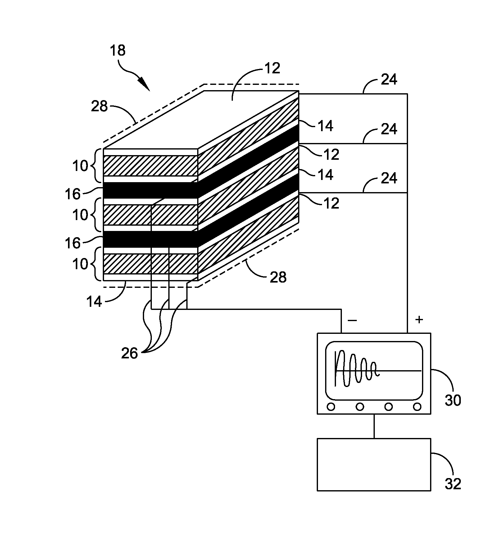
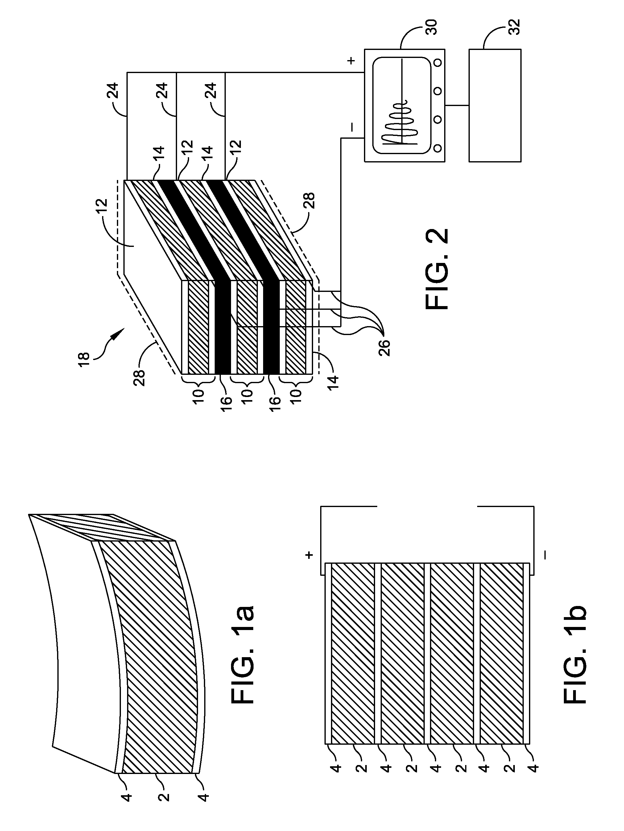
[0017]Referring now to FIG. 2 there is illustrated several Ionic Polymer Metal Composite (IPMC) sections 10 each section having a top conductive surface 12 and a bottom conductive surface 14. There is also illustrated multiple dielectric sections 16. In a preferred embodiment, the dielectric section 16 is made of a thin flexible light weight material. An example of dielectric section 16 is electrical insulating adhesive tape.

[0018]The IPMC sections 10 are stacked vertically in a modified morphing arrangement with a dielectric section 16 between the top conductive surface 12 of an IPMC section 10 below it and the bottom conductive surface 14 of an IPMC section 10 above it to prevent electrical conduction between the two surfaces. This modified morphing arrangement creates a multilayer configuration 18 of IPMC sections 10 and dielectric sections 16.

[0019]Each of the top conductive surfaces 12 of each IPMC section 10 serves as a positive electrode in the multilayer configuration 18. Ea...


PUM


Abstract

A quasi-static bend sensor is taught that comprises a layering of a plurality of ionic polymer metal composite (IPMC) sections with intervening dielectric sections in a vertical stack configuration. The IPMC sections are electrically connected in parallel. The surface of the stack is coated with high-purity synthetic isoparaffins for polymer hydration to increase step response consistency. Finally, the vertical stack configuration is electrically connected to an electric field measurement device and a linear quadratic regulator based controller for reducing settling time.

Description

STATEMENT OF GOVERNMENT INTEREST[0001]The invention described herein may be manufactured and used by or for the Government of the United States of America for governmental purposes without the payment of any royalties thereon or therefore.CROSS REFERENCE TO OTHER RELATED APPLICATIONS[0002]Not applicable.BACKGROUND OF THE INVENTION[0003](1) Field of the Invention[0004]The present invention relates to electro-active materials, and more specifically to devices composed of ionic polymer metal composites (IPMC) for use as bend sensors or velocity sensors.[0005](2) Description of the Prior Art[0006]Electro-active materials are subject to mechanical deformation in response to external electrical stimulation or of electric current generation in response to externally induced strain. Electro-active materials are most often used as energy harvesting devices, active noise cancellation, vibration control, microphones and acoustic transducers. Electro-active polymers are also being studied for t...

Claims


Application Information

Patent Timeline
IPC IPC(8): G01B7/16G01B5/30G01F25/00G01L1/00
CPCG01B7/16G01L1/005G01F1/28
Inventor LACOMB, JULIELACOMB, RONALD
Owner THE UNITED STATES OF AMERICA AS REPRESENTED BY THE SECRETARY OF THE NAVY
Why Eureka
Try Eureka