Electromagnetic pump with frequency converter circuit

a frequency converter and electromagnet pump technology, applied in the direction of motor/generator/converter stopper, positive displacement liquid engine, dynamo-electric converter control, etc., can solve the problems of high power consumption, large bulk, noisy, etc., and achieve less electric consumption, less noise, and low power consumption

Inactive Publication Date: 2013-07-09
CHIOU JACKEY
View PDF9 Cites 6 Cited by
  • Summary
  • Abstract
  • Description
  • Claims
  • Application Information

AI Technical Summary

Benefits of technology

[0006]In view of that the medical apparatus and instruments, such as snot suction device, lattices suction device, nose cleaner, atomizer, teeth cleaner, tongue cleaner, and etc., are required to have the advantages of low power consumption, less electric consumption, less noisy, compact size, prevention of generating high-heat, waterproof, and etc., the applicant of the present invention invents an electromagnetic pump to achieve the advantages mentioned above and below after a series of researches and experiments.
[0008]The invention is advantageous in that it provides an electromagnetic pump with a N-phase or S-phase frequency converter circuit, which could accelerate the swing speed of the swing arm swinging outwardly to further increase the suction pressure of the electromagnetic pump or accelerate the swing speed of the swing arm swinging inwardly to further increase the discharge pressure of the electromagnetic pump, thereby the medical apparatus and instruments using the electromagnetic pump as power source could be used with any proper electrical power in any place.
[0012]The oscillator circuit could be connected to a button or a keypad, which is arranged to adjust the oscillating frequency of the oscillator circuit. In another embodiment of the present invention, the frequency converter circuit further comprises a modulation circuit which generates a single-phase oscillating signal. The N-phase stimulus signal and the S-phase stimulus signal generated in the bistable circuit are mixed with the single-phase oscillating signal respectively to enhance the N-phase stimulus signal while balancing the S-phase stimulus signal or to enhance the S-phase stimulus signal while balance the N-phase stimulus signal. The enhancement of the magnetic field strength of the N-phase of the electromagnetic device respectively further causes the swing arms swinging outwardly with a higher speed and a bigger force and swinging inwardly with a lower speed and a smaller force, thereby the suction pressure of the electromagnetic pump is increased and the discharge pressure of the electromagnetic pump is decreased. The enhancement of the magnetic field strength of the S-phase of the electromagnetic device respectively further causes the swing arms swinging inwardly with a lower speed and a smaller force and swinging outwardly with a higher speed and a bigger force, thereby the discharge pressure of the electromagnetic pump is increased and the suction pressure of the electromagnetic pump is decreased. The modulation circuit is connected to a button or a keypad, which is arranged to activate or adjust the modulation circuit. The DC inputted into the frequency converter circuit could be supplied by an in-car cigarette lighter, by a battery, or by a transformer rectifier unit.

Problems solved by technology

As the device in the first prior art is a device with multiple functions, it is safe to use it for atomization treatment; however, when it is used to suction the snot, it might hurt the nasal cavity due to the over suction force, and that when it is used to clean the nasal cavity, it might cause a choke due to the over discharge force.
Besides, the motor has a lot of defects, such as high power consumption, big bulk, a lot of noise, too big suction force, too big discharge force, high-heat, short service life, unbearable of wetting.
Hence, the device is not a proper power source for the medical apparatus and instruments that are required to contact with human body.
It means that due to the limitations mentioned above, the suction pressure, the suction flow, the discharge pressure, and the discharge flow of the current electromagnetic pump could not be adjusted according to the required pressure and flow.

Method used


Image

  • Electromagnetic pump with frequency converter circuit
  • Electromagnetic pump with frequency converter circuit
  • Electromagnetic pump with frequency converter circuit

Examples


Embodiment Construction

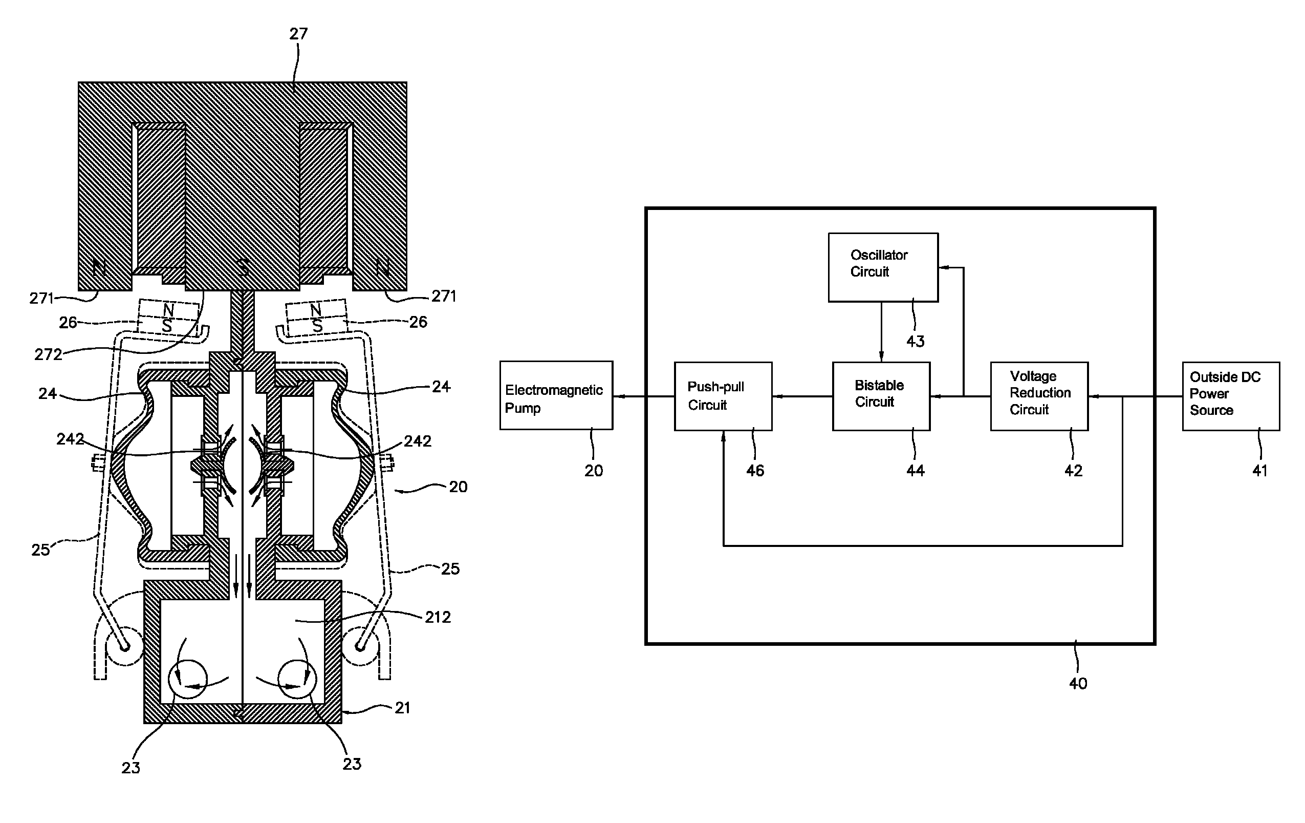
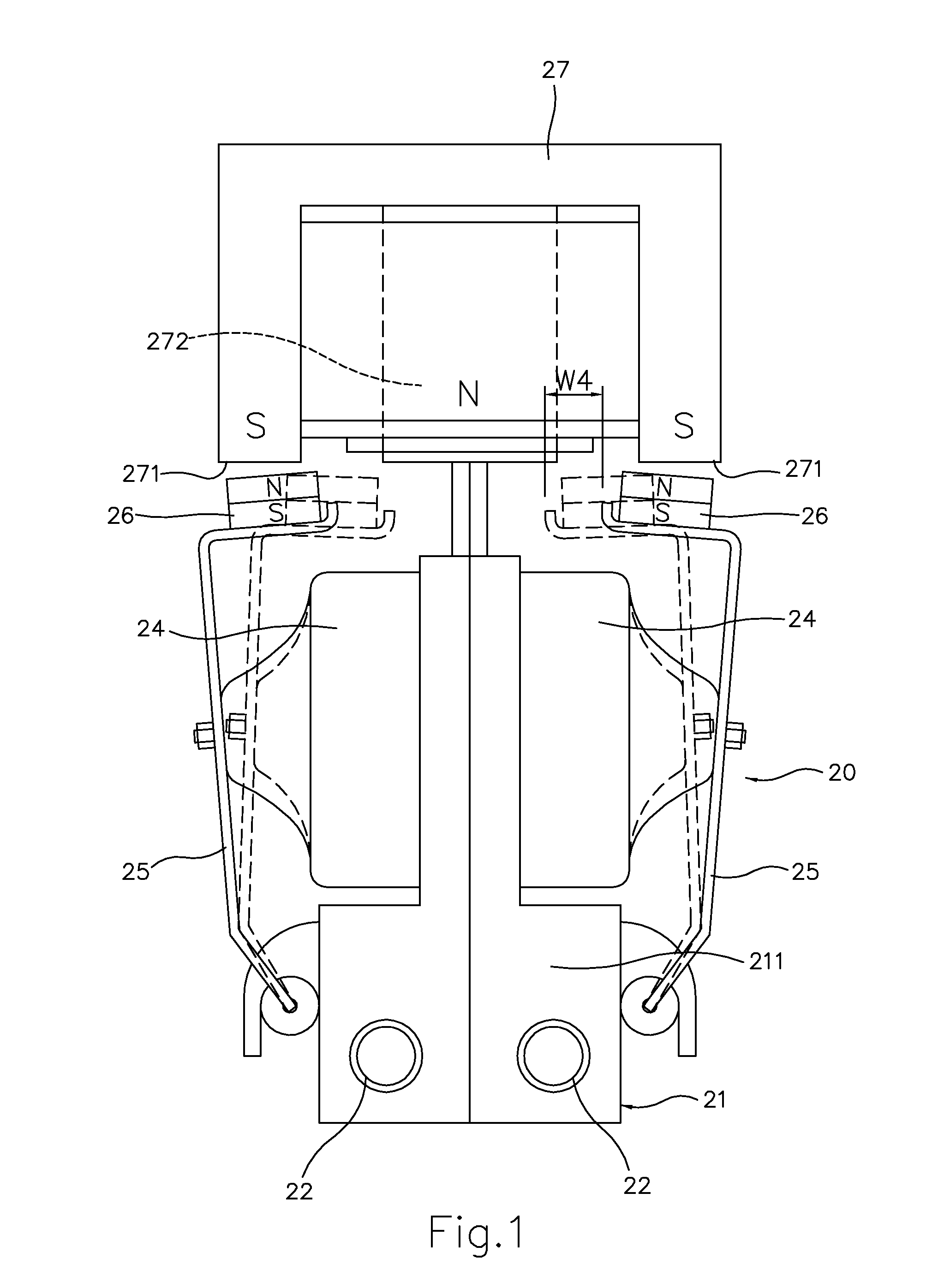
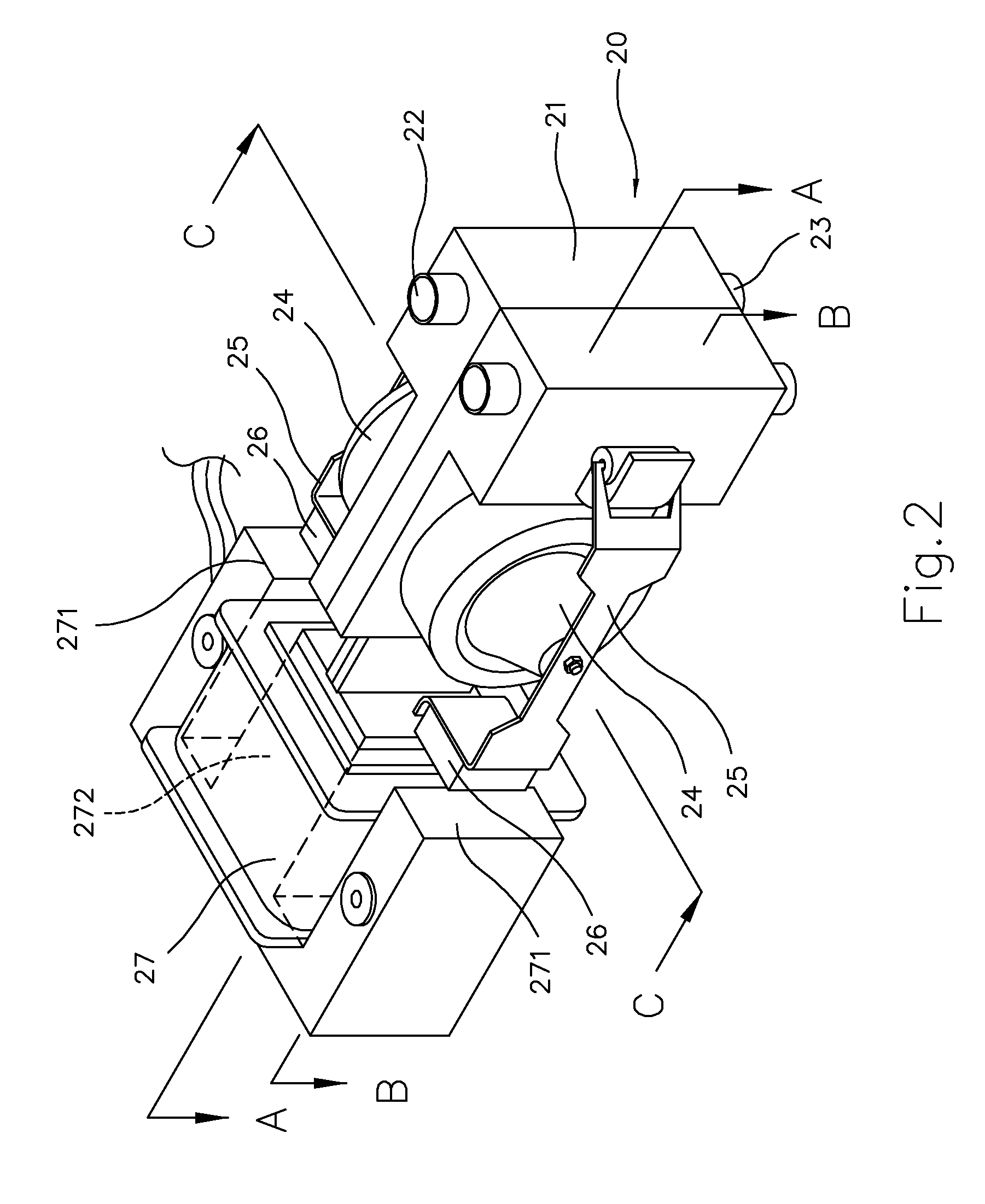
[0049]Referring to FIGS. 2 to 6, the electromagnetic pump 20 of the present invention comprises an electromagnetic device 27 surrounded with coils on one side and a pump housing 21 on the other side. Each of two outside surfaces of the pump housing 21 provides a stretchable and elastic bladder 24 which further provides an swing arm 25 thereon, wherein one end of each of the swing arms 25 is pivotally mounted on the outer side of the pump housing 21 while a magnetic member 26 is provided on the other end of each swing arm 25 with a distance from the electromagnetic device 27. The inside of the pump housing 21 is divided into two chambers, including a first chamber 211 in the upper portion and a second chamber 212 in the lower portion. The first chamber 211 is communicated with two inlet tubes 22 and the second chamber 212 is communicated with the outlet tube 23.

[0050]Referring to FIGS. 4 and 5, the electromagnetic device 27 has two side magnetic members 271 and a middle magnetic memb...


PUM


Abstract

An electromagnetic pump has a frequency converter circuit for driving the electromagnetic pump, wherein the frequency converter circuit comprises an oscillator circuit, a bistable circuit and a push-pull circuit. The oscillator circuit oscillates to transform DC into a single-phase oscillating signal. The bistable circuit splits the single-phase oscillating signal into a N-phase stimulus signal and a S-phase stimulus signal. The push-pull circuit amplifies and transports the N-phase stimulus signal and the S-phase stimulus signal to the electromagnetic pump to make the swing arms of the electromagnetic pump swinging effectively, wherein the swing speed, the swing frequency and the swing amplitude of the swing arms vary with the change of the oscillation frequency of the oscillator circuit. Thereby, the suction pressure and the discharge pressure of the electromagnetic pump could further be adjusted higher or lower, wherein said frequency converter circuit comprises a modulation circuit, which could change the swing speed of the swing arms swinging outwardly or inwardly to further increase or decrease the suction pressure or the discharge pressure.

Description

BACKGROUND OF THE PRESENT INVENTION[0001]1. Field of Invention[0002]The present invention relates to electromagnetic pump, and more particularly to an electromagnetic pump with a frequency converter circuit, wherein the swinging speed, frequency and amplitude of the swing arms thereof are adjustable to change the suction pressure or the discharge pressure thereof.[0003]2. Description of Related Arts[0004]Taiwan patent application No. 092217183 “Nasal Cavity Cleaning and Atomizing Treatment Device” (hereinafter, the first prior art) discloses a device for suctioning snot, cleaning the nasal cavity and atomizing a fluid with medicine to the nasal cavity to treat the sickness of nasopharynx. The device comprises a chamber and a bladder expending and compressing to respectively draw a gas into the chamber through an inlet and discharge the gas from the chamber through an outlet. If a suction device is connected to the inlet, the device will become a device with the function of suctionin...

Claims


Application Information

Patent Timeline
Patent Type & Authority Patents(United States)
IPC IPC(8): H02K41/02
CPCF04B17/042F04B43/04F04B45/027
Inventor WANG, MING YANG
Owner CHIOU JACKEY
Why Eureka
Try Eureka