System for detecting or estimating center-of-gravity, lateral rollover limit or cargo weight

a technology of center-of-gravity which is applied in the field of center-of-gravity detection systems and lateral rollover limit velocity estimation systems, and cargo weight estimation systems, which can solve problems such as becoming social problems

Active Publication Date: 2013-07-09
TOKYO UNIV OF MANNE SCI & TECH
View PDF26 Cites 13 Cited by
  • Summary
  • Abstract
  • Description
  • Claims
  • Application Information

AI Technical Summary

Benefits of technology

[0057]In accordance with the first aspect of the present invention, there is provided a center-of-gravity detection system capable of properly deriving the 3D center-of-gravity location of a vehicle capable of carrying cargo and adapted to be towed by a towing vehicle.
[0058]In addition, in accordance with the second aspect of the present invention, there is also provided a lateral rollover limit velocity estimation system capable of properly deriving, by means of the 3D center-of-gravity location of a vehicle which is towed by a towing vehicle, the lateral rollover limit velocity of the vehicle in response to the curvature radius of a curved road section of a road along which the towed vehicle travels.
[0059]In addition, in accordance with the third aspect of the present invention, there is also provided a cargo weight estimation system capable of properly deriving, by means of the 3D center-of-gravity location of a vehicle capable of carrying cargo and adapted to be towed by a towing vehicle, the weight of the cargo.

Problems solved by technology

Incidentally, such container cargo is generally transported without having checked its condition of loading in the container and, as a result, various inconveniences caused by container transport vehicles have been heretofore viewed as social issues.
For example, situations resulting from the biased loading of cargo in the container (e.g., cargo pile collapse / cargo falling occurring when the container door is opened and unstable travel motions of the container transport vehicle when travelling along a curved road section) are becoming social problems.

Method used


Image

  • System for detecting or estimating center-of-gravity, lateral rollover limit or cargo weight
  • System for detecting or estimating center-of-gravity, lateral rollover limit or cargo weight
  • System for detecting or estimating center-of-gravity, lateral rollover limit or cargo weight

Examples


first embodiment

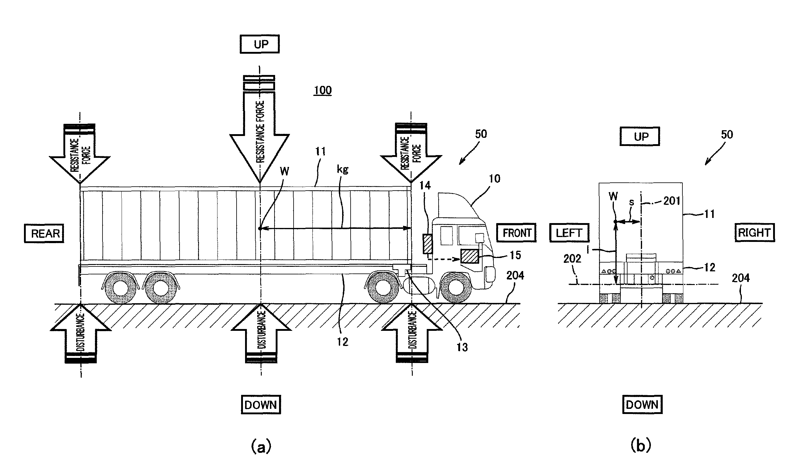
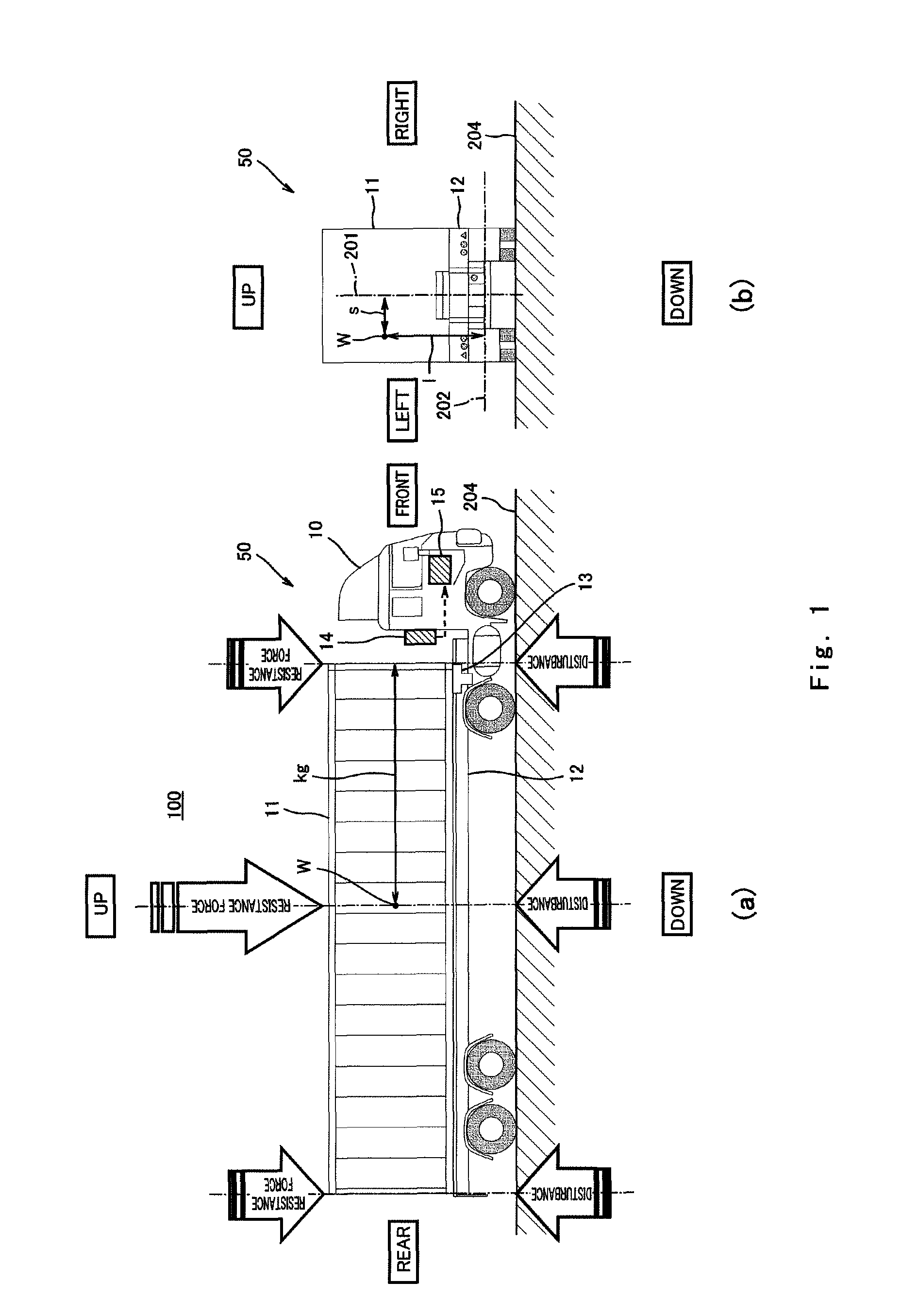
[0083]FIG. 1 is a schematic illustration showing an example of the configuration of a center-of-gravity detection system according to a first embodiment of the present invention. FIG. 1(a) is a view of the center-of-gravity detection system, as viewed from the width direction (from one side) of a container cargo vehicle. FIG. 1(b) is a view of the center-of-gravity detection system, as viewed from the rear side of the container cargo vehicle.

[0084]Also note that in the drawings, for the sake of convenience of the following description, the direction in which the self (tare) weight of the container cargo vehicle is applied is referred to as the “vertical direction”, the width direction of the container cargo vehicle is referred to as the “horizontal direction”, and the travel direction of the container cargo vehicle is referred to as the “front / rear direction”.

[0085]Referring to FIG. 1(a), there is shown a center-of-gravity detection system 100 which includes a container transport ve...

example 1

[0219]With a view to backing up the validity of the method of deriving the 3D center-of-gravity location of the container cargo vehicle by means of the center-of-gravity detection system 100 of the first embodiment, a first verification experiment (center-of-gravity measurement) by use of an actual vehicle was conducted on a public road in Port Island at Port of Kobe on Apr. 12, 2006. In addition, the present verification experiment was carried out such that, in order that the present technology may not become public knowledge, the theoretical expressions of the present technology were stored as a program in a “black box” manner in the internal memory of a personal computer.

[0220]The procedure of the present verification experiment is as follows. In the first place, a standard 40-feet container was loaded with dummy cargo for experimental use of about 9.5 tons (about 9.5×10³ kg). In regard to the condition of loading of the dummy cargo, the length kg from the container front section...

second embodiment

[0233]FIG. 10 is an outline illustration showing an example of the configuration of a lateral rollover limit velocity estimation system according to a second embodiment of the invention. FIG. 10(a) is a view of the estimation system as viewed from the width direction (sideways) of the container cargo vehicle. FIG. 10(b) is a view of the estimation system as viewed from the rear side of the container cargo vehicle.

[0234]Also note that in the drawings, for the sake of convenience of the following description, the direction in which the self-weight of the container cargo vehicle is applied is referred to as the “vertical direction”, the width direction of the container cargo vehicle is referred to as the “horizontal direction”, and the travel direction of the container cargo vehicle is referred to as the “front / rear direction”.

[0235]In addition, with respect to the lateral rollover limit velocity estimation system 110 according to the present embodiment, components corresponding to tho...


PUM

PropertyMeasurementUnit
horizontal lengthaaaaaaaaaa
curvature radiusaaaaaaaaaa
velocityaaaaaaaaaa

Abstract

A center-of-gravity detection system includes a vehicle capable of carrying cargo and adapted to be towed by a towing vehicle, a shake detector configured to detect shakes in the directions of the self-weight and width of the towed vehicle during travel of the towed vehicle, and an arithmetic unit. The arithmetic unit is configured to derive, based upon physical quantities that correlate with the shakes, the location of the center of gravity, in three-dimensional space, of the towed vehicle.

Description

TECHNICAL FIELD[0001]The present invention relates to center-of-gravity detection systems and lateral rollover limit velocity estimation systems, and cargo weight estimation systems for vehicles capable of carrying cargo and adapted to be towed by towing vehicles. More particularly, this invention relates to technologies for finding the location of the center of gravity in three-dimensional space of a container cargo vehicle towed and transported by a towing vehicle, for finding the lateral rollover limit velocity of such a vehicle on a curved road section of a road by means of the location of the center of gravity in three-dimensional space, and for finding the weight of cargo.BACKGROUND ART[0002]Generally, container cargo, commercially traded in international imports and exports, is placed, together with the container, on a carriage called a container chassis in the domestic distribution network. The container chassis is towed and transported by a towing vehicle such as a tractor,...

Claims


Application Information

Patent Timeline
Patent Type & Authority Patents(United States)
IPC IPC(8): G06F17/10
CPCB60W40/12G01G23/3728G01M1/122G01G19/086
Inventor WATANABE, YUTAKA
Owner TOKYO UNIV OF MANNE SCI & TECH
Why Eureka
Try Eureka