Personal aircraft

a personal aircraft and rotor technology, applied in the field of personal aircraft, can solve the problems of requiring maintenance, rotors are typically quite complex, and utilize mechanically complex systems to control both the collective and cyclic blade angles, etc., to achieve high compactness, safety, quiet and efficient, and easy control

Active Publication Date: 2013-07-16
WISK AERO LLC
View PDF4 Cites 52 Cited by
  • Summary
  • Abstract
  • Description
  • Claims
  • Application Information

AI Technical Summary

Benefits of technology

[0008]The described embodiments provide a personal aircraft with a configuration that is safe, quiet, and efficient, as well as easy to control, highly compact, and able to accomplish vertical takeoff and landing with transition to and from forward flight. In one embodiment, the aircraft configuration includes multiple rotors oriented to provide vertical thrust for lift and control during takeoff, transition to and from forward flight, and landing. The rotors are attached to the airframe in fixed, non-planar orientations. The orientations of rotors provide lateral and, in some embodiments, fore and aft control of aircraft without requiring a change of attitude, and minimize disturbances to the flow when the aircraft is cruising. In various embodiments, the rotors have forward, backwards, left, and right orientations, and are located longitudinally along the port and starboard sides of the fuselage, with two or more rotors located on each side.
[0009]The fuselage carries a variable-weight payload. The aircraft has tandem wings at the front and rear of the vehicle. The wings provide lift and control during cruise, and one or more propellers provide forward thrust. The combination of vertical lift rotors and front and rear tandem wings bound the rotors, permitting movement in the aircraft's center of gravity while still enabling the vehicle to maintain vertical and horizontal flight control. The forward and rear wings are also located to provide a boundary to avoid foreign object damage (FOD) to the lift rotors. The control surfaces, which include elevator and ailerons, are usable to compensate for changes in CG of the aircraft during flight by adjusting the center of lift, in addition to changing angle of attack and attitude. The vertical lift rotors are arranged around the CG, and the thrust of each rotor is adjustable, which permits the relocation of the center of lift in vertical flight if the CG shifts.
[0010]Due to the multiple number and independence of the vertical lift rotors, the vertical thrust is redundant and thrust and control remain available even with the failure of any single rotor. Since there are multiple vertical rotors that provide large control forces, the rotors are smaller, with faster response rates for operation even in gusty wind conditions. In one embodiment, a separate electric motor and controller powers each vertical lift rotor, in order to provide lift system redundancy from failure of one or more lifting rotors. In other embodiments, the vertical thrust rotors are embedded in ducts that conceal them and provide increased lift. Other embodiments are relatively open with protective shrouding to act as guards to prevent contact with other objects and prevent FOD to the rotors. The protective shielding in combination with in-line vertical lift rotors provide low cruise drag for efficient flight. Low tip speed vertical lift rotors are used in various embodiments to produce low community noise levels during takeoff, transition, and landing. Embodiments with a low front wing and high rear wing with winglets provide high aerodynamic efficiency while also providing yaw stability for the aircraft. In some embodiments, the wings fold to provide a compact vehicle footprint when in hover or while on the ground. Some embodiments of the wing have control surfaces only on the inner part of the wing fold so that no articulating control linkages are required. Since the lift rotors that are used for vertical lift are separate from the forward thrust propellers, each is optimized for its specific operating conditions. Such a vehicle can be used for either piloted or unpiloted embodiments across a range of occupant sizes or payloads.

Problems solved by technology

For the rotors to perform this dual function across a range of airspeeds, the rotors are typically quite complex.
Additionally, they utilize mechanically complex systems to control both the collective and cyclic blade angles.
Such rotors are mechanically complex and require maintenance.
The rotors generally rotate at a low speed; this results in heavy transmissions between the rotor and motor.
Because of the mechanical complexity across the entire vehicle system, many parts are single points of failure.
Due to the multiple number and independence of the vertical lift rotors, the vertical thrust is redundant and thrust and control remain available even with the failure of any single rotor.

Method used


Image

  • Personal aircraft
  • Personal aircraft
  • Personal aircraft

Examples


Embodiment Construction

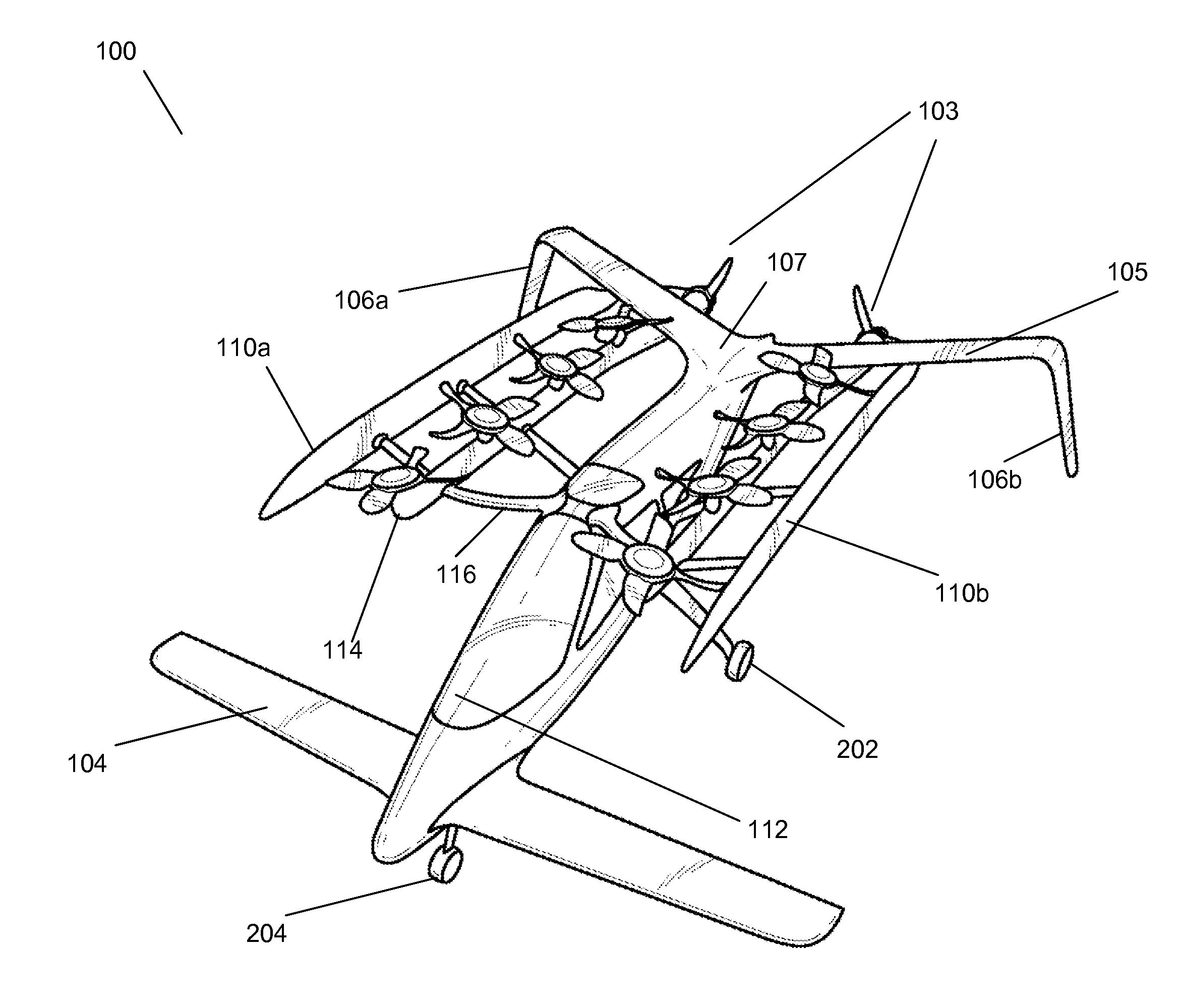
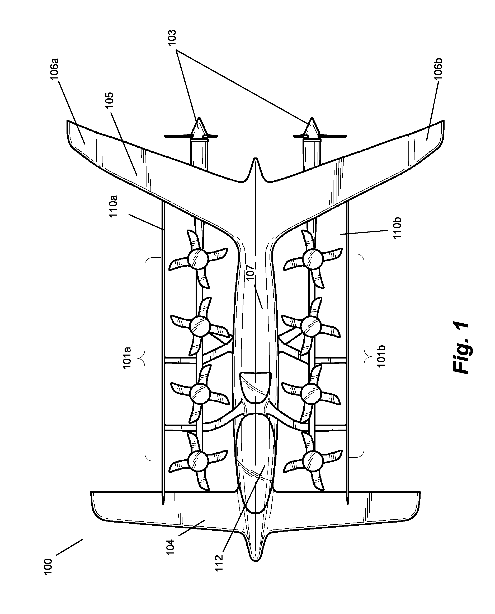
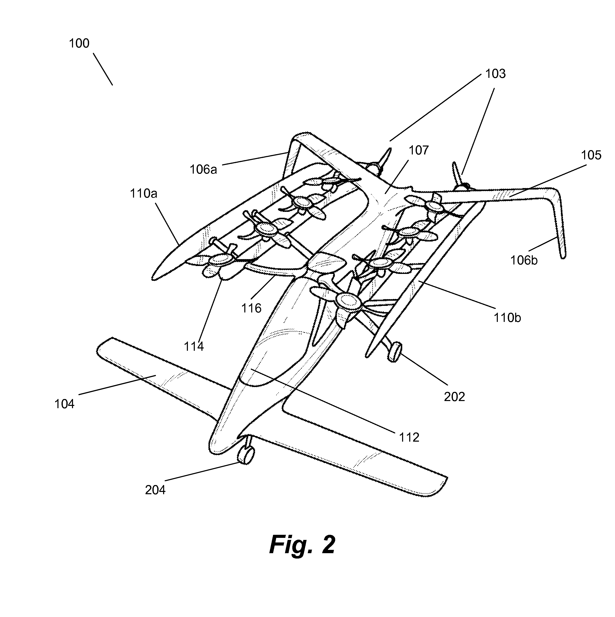
[0017]FIG. 1 illustrates a personal aircraft 100 in accordance with one embodiment. Aircraft 100 includes vertical lift rotor assemblies 101a and 101b (generally, 101) with fixed orientations; forward flight propellers 103; a forward wing 104; a rear wing 105 having winglets 106a and 106b (generally, 106); fences 110a and 110b (generally 110), a cockpit area 112 and a fuselage 107. Fuselage 107 also includes landing gear, a flight computer and power source (not shown), each of which is described further below. FIG. 2 illustrates a second view of personal aircraft 100, including propulsion booms 114, port-side main landing gear 202 and forward landing gear 204. FIG. 3 illustrates a front view of personal aircraft 100, in which port landing gear 202a, starboard landing gear 202b and nose gear 204 are visible. FIG. 4 illustrates a view of the left (port) side of aircraft 100 in accordance with one embodiment.

[0018]In various embodiments, aircraft 100 is sized to accommodate a single pi...


PUM


Abstract

A safe, quiet, easy to control, efficient, and compact aircraft configuration is enabled through the combination of multiple vertical lift rotors, tandem wings, and forward thrust propellers. The vertical lift rotors, in combination with a front and rear wing, permits a balancing of the center of lift with the center of gravity for both vertical and horizontal flight. This wing and multiple rotor system has the ability to tolerate a relatively large variation of the payload weight for hover, transition, or cruise flight while also providing vertical thrust redundancy. The propulsion system uses multiple lift rotors and forward thrust propellers of a small enough size to be shielded from potential blade strike and provide increased perceived and real safety to the passengers. Using multiple independent rotors provides redundancy and the elimination of single point failure modes that can make the vehicle non-operable in flight.

Description

CROSS-REFERENCE TO RELATED APPLICATIONS[0001]This application claims the benefit of provisional application No. 61 / 509,530, filed on Jul. 19, 2011, which is incorporated by reference herein in its entirety.BACKGROUND[0002]1. Field of the Invention[0003]This disclosure relates generally to a personal aircraft configured to provide safe operations while achieving robust control. In particular, the described embodiments include an aircraft with vertical takeoff and landing capability, and that provides vertical and horizontal thrust in a controlled fashion for hover, transition and cruise flight.[0004]2. Description of Related Art[0005]Taking off and landing vertically, instead of using a runway to develop sufficient velocity on the ground for wings to provide adequate lift, requires an aircraft to provide both vertical and forward thrust. Thrust produced in the vertical direction provides lift to the vehicle; thrust produced horizontally provides forward movement. A vertical takeoff a...

Claims


Application Information

Patent Timeline
Patent Type & Authority Patents(United States)
IPC IPC(8): B64C27/22
CPCB64C3/16B64C29/0025B64C29/00B64D31/00B64C39/12Y02T50/12Y02T50/10B64C11/46
Inventor KROO, ILAN
Owner WISK AERO LLC
Why Eureka
Try Eureka