Method of internally restoring a leaking pipe

a leakage pipe and internal restoration technology, applied in the field of pipes, can solve the problems of coating being forced out of the leak opening without sealing, the inability of the process to seal leaks, and the inability to seal other than the smallest leaks in the system of pipes with the process

Active Publication Date: 2013-07-16
TERRY ROY A +2
View PDF10 Cites 15 Cited by
  • Summary
  • Abstract
  • Description
  • Claims
  • Application Information

AI Technical Summary

Benefits of technology

[0020]It is yet a further objective of the present invention to provide a pipe restoration method, which precisely measures and controls the volume of airflow through a pipe.
[0021]It is yet a further objective of the present invention to provide a pipe restoration method, which precisely controls the temperature of the airflow through a pipe.

Problems solved by technology

The real life application of the process to restore aging building water systems has had many challenges.
The difficulty of insuring that the dry sandblasting material is cleared from the pipe system after the cleaning operation; restriction and plugging of pipe tee's and pipe intersections with excess coating material; and the inability of the process to seal leaks is well known to those in the art.
To seal other than the smallest of leaks in systems of pipes with the Process has not been possible.
Compressed air application of an internal liquid epoxy coating results in the coating being forced out the leak opening without sealing the leak.
If the known problem of clearing the dry cleaning media proved problematic in the prior art, the removal of the bentonite and filler loaded solution suggested by Naf would be at least equally a challenge if not impossible.
It will not be practical to clear a pipe system once this material is introduced and allowed to set to the point of sealing the leaks.
The uncleared sealing media taught by Naf will necessarily result in restricted and plugged pipe sections.
The individual ‘shots’ of coating material introduced into each successive outlet are not measured to clear the system of pipes, just to coat an individual portion of the system, thus the filler load of each ‘shot’ of coating will remain within the system causing a significant reduction in internal pipe diameter, compromise the intended lining thickness, and result in an inferior finished product.

Method used


Image

  • Method of internally restoring a leaking pipe
  • Method of internally restoring a leaking pipe
  • Method of internally restoring a leaking pipe

Examples


Embodiment Construction

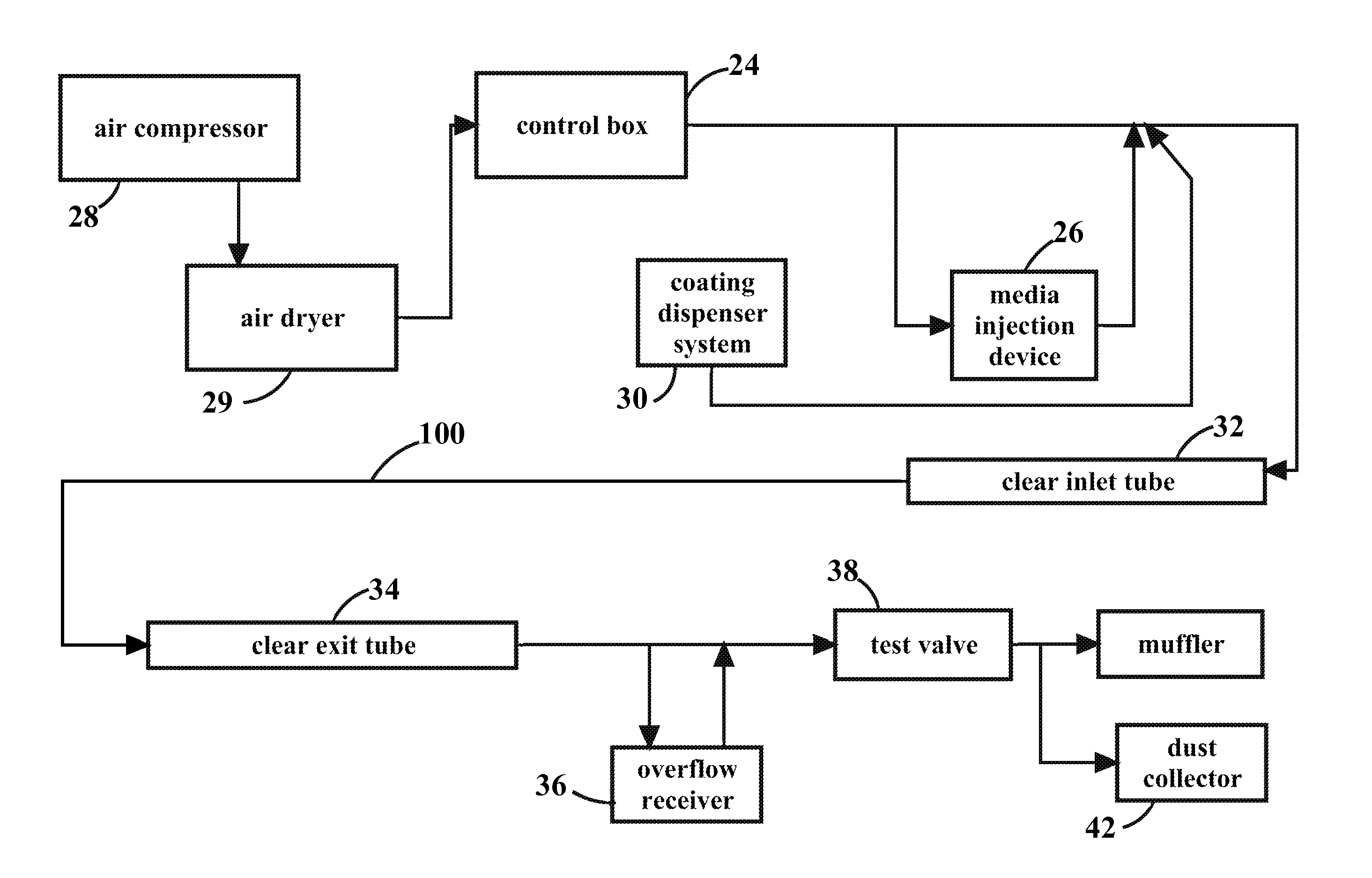
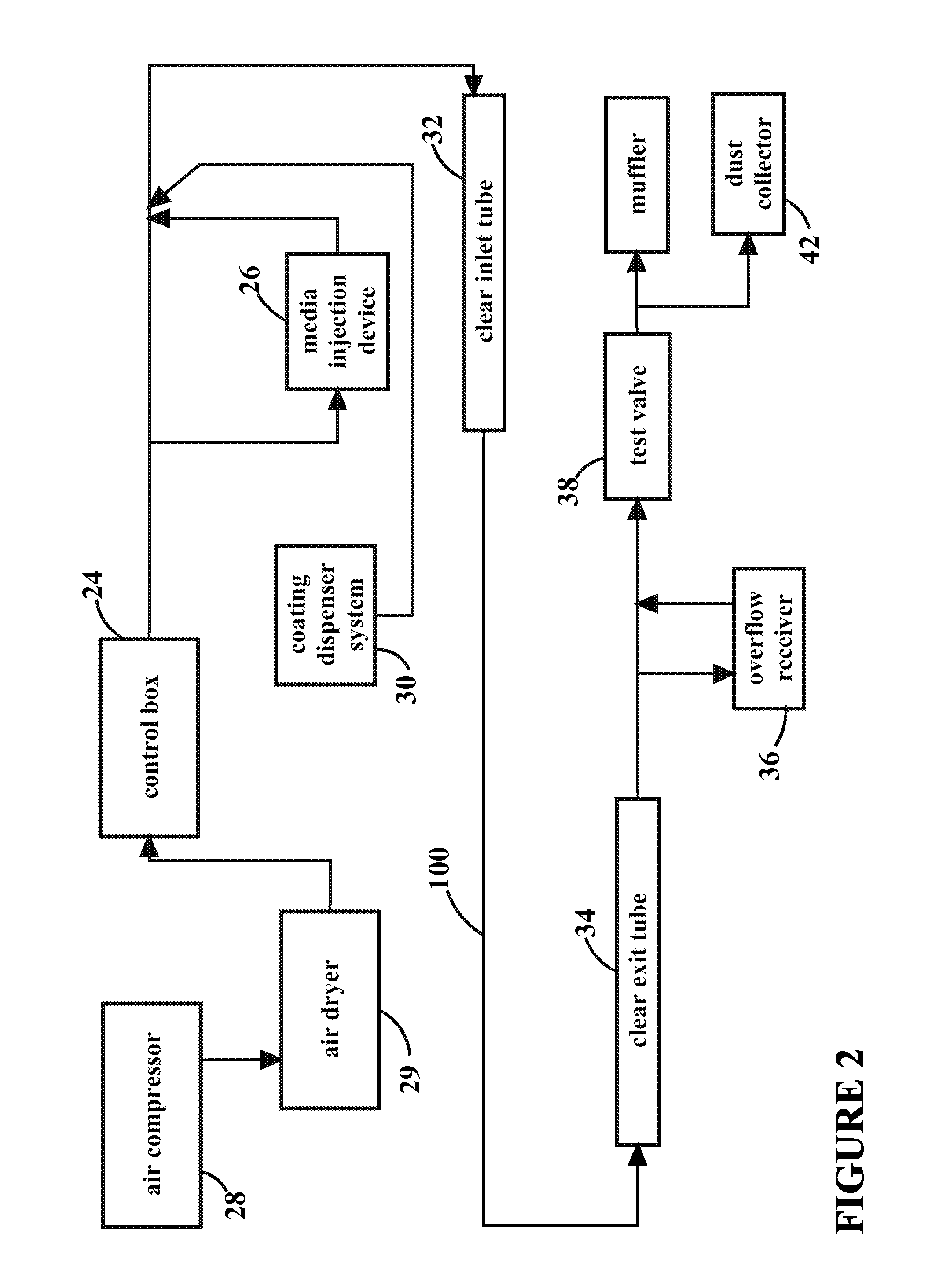
[0030]With reference now to the drawings, and particularly to FIG. 1, there is shown a flow chart of a pipe restoration method 1. With reference to FIG. 2, the pipe restoration system 1 has been found to be satisfactory in repairing a leaking pipe 100, which is a part of a system of pipes for carrying pressurized water in a building. The leaking pipe 100 is commonly encased with a concrete foundation or floor of the building. The leaking pipe is typically a soft copper water pipe experiencing pinhole leaks due to internal pitting corrosion and the leaking pipe 100 is between ½″ and 2″ in diameter. However, the pipe restoration method 1 should not be limited to the previously recited parameters.

[0031]With reference to FIGS. 3-4, the pipe restoration method 1 preferably includes the steps of separating a leaking pipe from a system of pipes in process block 10, drying an interior surface of a leaking pipe in process block 11; measuring the airflow through the leak in process block 12; ...


PUM

PropertyMeasurementUnit
flow rateaaaaaaaaaa
pressureaaaaaaaaaa
temperatureaaaaaaaaaa

Abstract

A method of internally restoring a pipe preferably includes the steps of isolating a leaking pipe from a system of pipes; drying an interior of a leaking pipe; measuring the airflow through the leak; cleaning the interior of the leaking pipe; pre-sealing a leak with a leak sealing media, measuring the leak flow rate after the pre-sealing; applying an internal protective coating process; and pressure testing the leaking pipe for leaks. The pipe restoration method preferably uses a control box, a media injection system, an air compressor and a coating dispensing system at an inlet of the leaking pipe. The pipe restoration method preferably uses a coating overflow receiver, a muffler and a dust collector at an exit of the leaking pipe. After the treatments, the leaking pipe becomes a restored pipe. The restored pipe is pressure tested for leaks at a working pressure rating of the pipe and reconnected to its piping system.

Description

BACKGROUND OF THE INVENTION[0001]1. Field of the Invention[0002]The present invention relates generally to pipes and more specifically to a method of internally restoring a pipe, which provides a cost effective alternative to replacing or making exterior repairs to the pipe.[0003]2. Discussion of the Prior Art[0004]A method of restoring small diameter pipe systems (the Process), utilizing compressed air for cleaning and internal coating pipes, has been well known worldwide since at least the late 1970′s. The Toyo Lining Company received an approval from the Japanese government to restore water pipe systems in 1981. Since 1987, the Naval Research Laboratory has been involved in the development and testing of coatings for the in-place lining of piping systems. The process is commonly known as the “Air-Sand” lining process and has been utilized by the Navy to restore and protect the piping in its ships and land-based facilities, both commercial and residential.[0005]The real life appli...

Claims


Application Information

Patent Timeline
Patent Type & Authority Patents(United States)
IPC IPC(8): B05D7/22
CPCB05D7/222F16L55/1003F16L58/1009B05D3/0413B05D2254/04B24C1/003B24C3/325Y10S118/10Y10S118/13B05C7/04B05C9/06B05C9/14
Inventor TERRY, ROY A.TERRY, RYAN A.TERRY, MICHAEL T.
Owner TERRY ROY A
Why Eureka
Try Eureka