Print through reduction in long fiber reinforced composites by addition of carbon nanotubes

a technology of carbon nanotubes and which is applied in the field of printing through reduction in long fiber reinforced composites by adding carbon nanotubes, can solve the problems of lower density, less strength and stiffness, and compatibility with other materials, and achieves a higher quality and minimizing the effect of printing through distortion in the surfa

Active Publication Date: 2013-07-16
GM GLOBAL TECH OPERATIONS LLC
View PDF14 Cites 10 Cited by
  • Summary
  • Abstract
  • Description
  • Claims
  • Application Information

AI Technical Summary

Benefits of technology

[0012]This invention provides a method for minimizing print through distortions in surfaces of woven fiber reinforced polymer composite articles. The invention is practiced so as to provide higher quality visible surface layers on polymer composite articles that otherwise benefit from the presence of extensive woven fiber reinforcement layers.
[0013]In accordance with embodiments of the invention, a preformed, moldable, polymer prepreg layer, reinforced with closely spaced, vertically oriented, carbon nanotubes is applied to an intended visible surface of the woven fiber-reinforced layup material. The woven fiber reinforced material makes up the body portion of the molded composite article, but the nanotube layer is sized and shaped to form one or more surfaces of the composite article. In contrast with the orientation of the woven fibers in the underlying polymer body layer(s), the carbon nanotubes are oriented transverse to the thickness of the comparatively thin applied covering polymer layer for the surface of the molded composite article. The woven fiber reinforced polymer portion and each covering polymer layer of oriented carbon nanotubes are shaped together and their polymer content cured together to form a durable composite article with smoother visible surfaces. The transverse orientation of the carbon nanotubes in the covering polymer layer reduces uneven shrinkage of surface regions and leaves a relatively smooth surface on the article that is mainly strengthened with the woven fibers. By addition of such a covering layer, the upper surface of the article is made more homogeneous, reducing the disparity in CTE and other properties between open and filled regions of the weave, which would otherwise lead to the observed print through.
[0014]Carbon nanotubes are hollow co-axial cylinders of carbon whose diameters are measured in nanometers or tens of nanometers, with lengths which may extend over tens of millimeters. They exhibit high strength and a low coefficient of thermal expansion (CTE) along their cylinder axis. Hence the thermal contraction of a vertically arranged carbon nanotube polymer composite will be greatly reduced compared to the thermal contraction of the polymer alone, further reducing the tendency for print through in the composite article.
[0022]The effectiveness of nanotube-polymer layer in controlling the distortion of the polymer will depend on the relative strengths of the nanotube-polymer composite and the polymer alone. It will also depend on the relative thicknesses of the nanotube-polymer layer and the polymer layer, generally equal to about 1.5 times the thickness of the tow after molding.

Problems solved by technology

This practice is applicable to many matrix materials including metals, ceramics and polymers, but is frequently employed with polymer matrices, which offer lesser strength and stiffness, but lower density, than either ceramics or metals.
For example, in assemblies where multiple materials are employed, compatibility, in performance or appearance, with other, different materials may be an issue.
During cool-down of the composite article this mismatch in CTE will induce stresses which will produce print through of the weave pattern, that is, surface distortions which mimic the weave pattern spacing.
These surface distortions, or print through of the fiber pattern, are clearly visible, particularly on a painted surface, and are unacceptable on any ‘show surface’ which may be viewed by a customer.

Method used


Image

  • Print through reduction in long fiber reinforced composites by addition of carbon nanotubes
  • Print through reduction in long fiber reinforced composites by addition of carbon nanotubes
  • Print through reduction in long fiber reinforced composites by addition of carbon nanotubes

Examples


Embodiment Construction

[0028]The following description of the embodiment(s) is merely exemplary in nature and is not intended to limit the invention, its application, or uses.

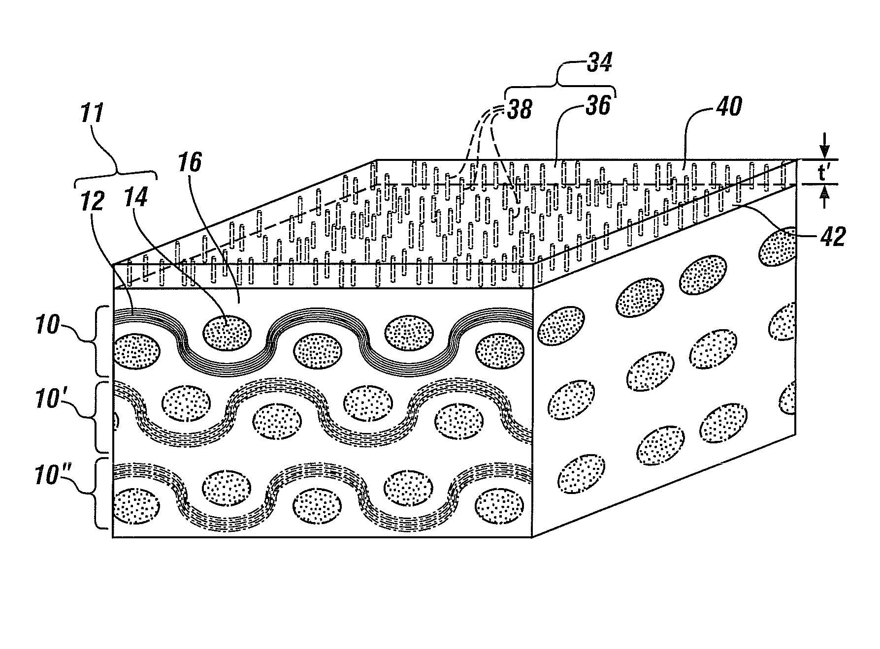
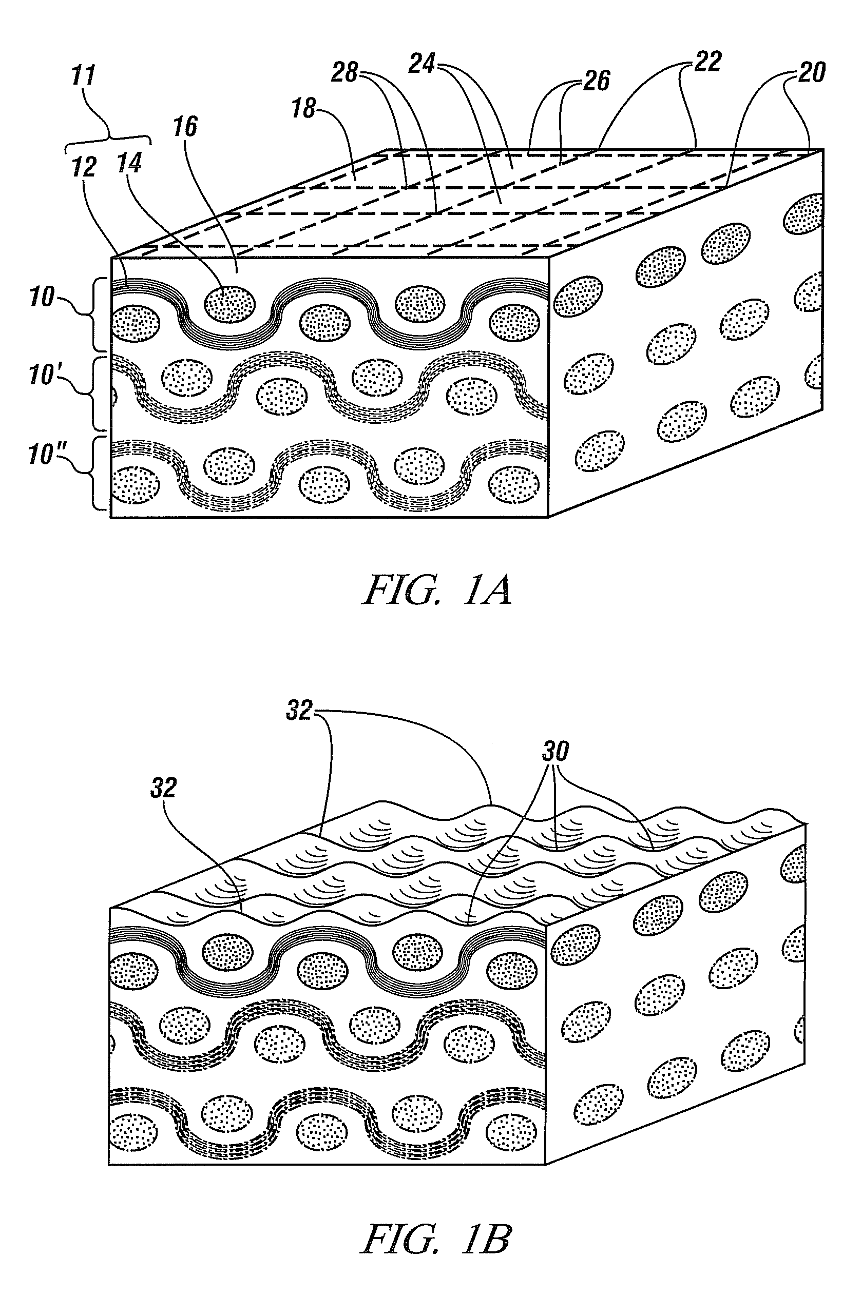
[0029]Carbon fibers ranging in diameter from about 1 micrometer to about 20 micrometers in diameter are popular reinforcements for high performance fiber reinforced polymer composites. Such fibers may be employed individually but, more commonly a number of such fibers will be gathered together to form a tow with a lateral dimension of between 500 micrometers to 1000 micrometers. A plurality of such tows may be arranged as warp and weft and woven together into a woven reinforcing mat. Such a mat may be impregnated with polymer resin or a B-staged polymer resin to form a prepreg and then assembled, with other prepregs, to form a layup. The layup may be shaped into a desired form, by application of pressure in a die, and cured, in the die, by application of heat to produce the desired carbon fiber reinforced polymer composite article.

[0...


PUM

PropertyMeasurementUnit
diameteraaaaaaaaaa
diameteraaaaaaaaaa
diameteraaaaaaaaaa

Abstract

Polymer articles are often reinforced by addition of fibers which may be assembled into a structured reinforcement such as a woven mat or sheet and the mat or sheet serves as the reinforcement. Such woven fiber-reinforced polymer composite articles may exhibit undesirable variations in surface height which mimic the geometry of the underlying reinforcements, a phenomenon known as print through. By forming, on the surface of the article, a relatively thin, layer of a compatible polymer incorporating closely-spaced, short, carbon nanotubes more or less uniformly dispersed throughout the layer and oriented normal to the article surface, print through may be reduced or eliminated. Methods for fabricating such an article are detailed.

Description

TECHNICAL FIELD[0001]This invention pertains to methods for reducing print through, or surface irregularities generally corresponding to the scale of the fiber weave, in molded polymer composite structures with woven long fiber reinforcements.BACKGROUND OF THE INVENTION[0002]It is well known that the strength and stiffness of a material may be improved by addition of strong and / or stiff reinforcements such as particles, chopped fibers or long fibers to form a composite structure. This practice is applicable to many matrix materials including metals, ceramics and polymers, but is frequently employed with polymer matrices, which offer lesser strength and stiffness, but lower density, than either ceramics or metals. Thus such a reinforced polymer structure may offer good strength and stiffness in combination with low mass.[0003]If low mass is of particular concern, the composite mass may be further minimized by using a higher strength and low density fiber reinforcement in addition to ...

Claims


Application Information

Patent Timeline
Patent Type & Authority Patents(United States)
IPC IPC(8): B29C70/44B29C45/14B29C65/00B32B27/04B32B5/08
CPCB29C70/025C08L63/00B29K2105/167B29K2995/0073Y10T428/24174C08K7/24C08K3/04Y10T442/3715Y10T442/3813
Inventor KIA, HAMID G.
Owner GM GLOBAL TECH OPERATIONS LLC
Why Eureka
Try Eureka