Remote passive sensing of a vibration signature using modulated light

a passive sensing and vibration signature technology, applied in the field of passive sensing of vibration signatures, can solve problems such as the illusion of measurement being taken, and achieve the effect of increasing the modulation frequency

Active Publication Date: 2013-07-16
THE UNITED STATES OF AMERICA AS REPRESETNED BY THE SEC OF THE AIR FORCE
View PDF2 Cites 6 Cited by
  • Summary
  • Abstract
  • Description
  • Claims
  • Application Information

AI Technical Summary

Benefits of technology

[0007]Briefly, the present invention detects minute changes in light intensity, commonly referred to as modulation, for light that is diffusely scattered from a surface that is coupled with a vibration. The invention measures the hypertemporal frequency of the modulation, i.e., a frequency greater than that which can be sensed by the human eye. Diffusely scattered light may be observed from any coupled surface, with no required orientation of the surface relative to the light source or a device sensing the reflected light. The invention operates at varying light levels, e.g., moonlight or sunlight. The lower the inertial mass of the light-scattering surface, the higher the modulation frequency that can be recovered. For example, a two-foot by two-foot sheet of 2 mm steel permits recovery of the entire audible frequency rage, i.e., up to 20,000 Hz.

Problems solved by technology

Furthermore, situations may call for concealing that a measurement is being taken.

Method used


Image

  • Remote passive sensing of a vibration signature using modulated light
  • Remote passive sensing of a vibration signature using modulated light
  • Remote passive sensing of a vibration signature using modulated light

Examples


Embodiment Construction

[0018]The optical information that may be gathered by the human eye is limited by the slow physiological response of the eye and mind. Visual processing of a time varying stimulus takes approximately 150 milliseconds. Consequently, periodic changes in an optical field more frequent than seven times per second will not be recognized. For example, one cannot see the 60 Hz flicker of fluorescent lighting, the rotating blades of a turbine, the turbulence of a rocket exhaust, or the fluctuations in glints of sunlight from leaves, because they all occur too rapidly for the human eye and mind to process and recognize. Optical information that occurs too rapidly for human recognition is commonly referred to as a hypertemporal image.

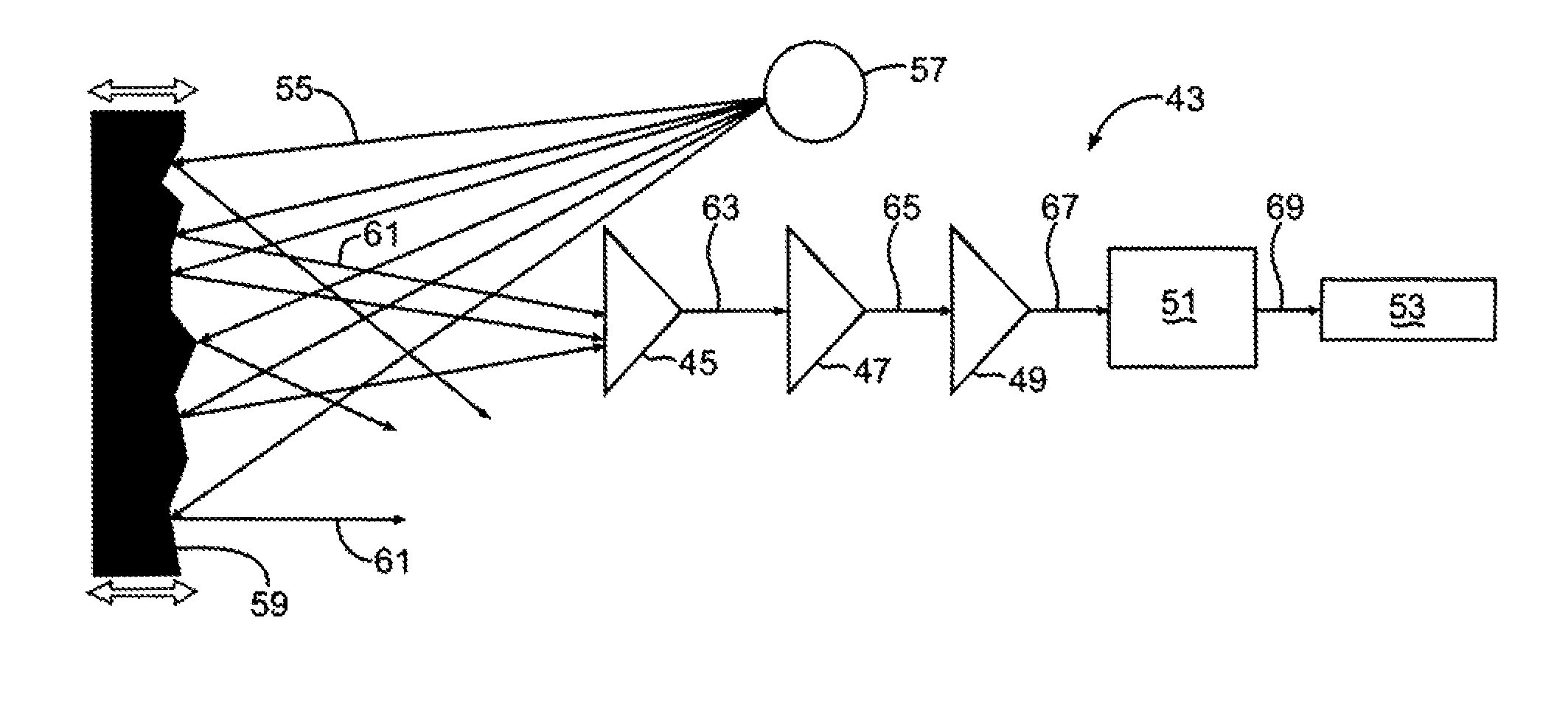
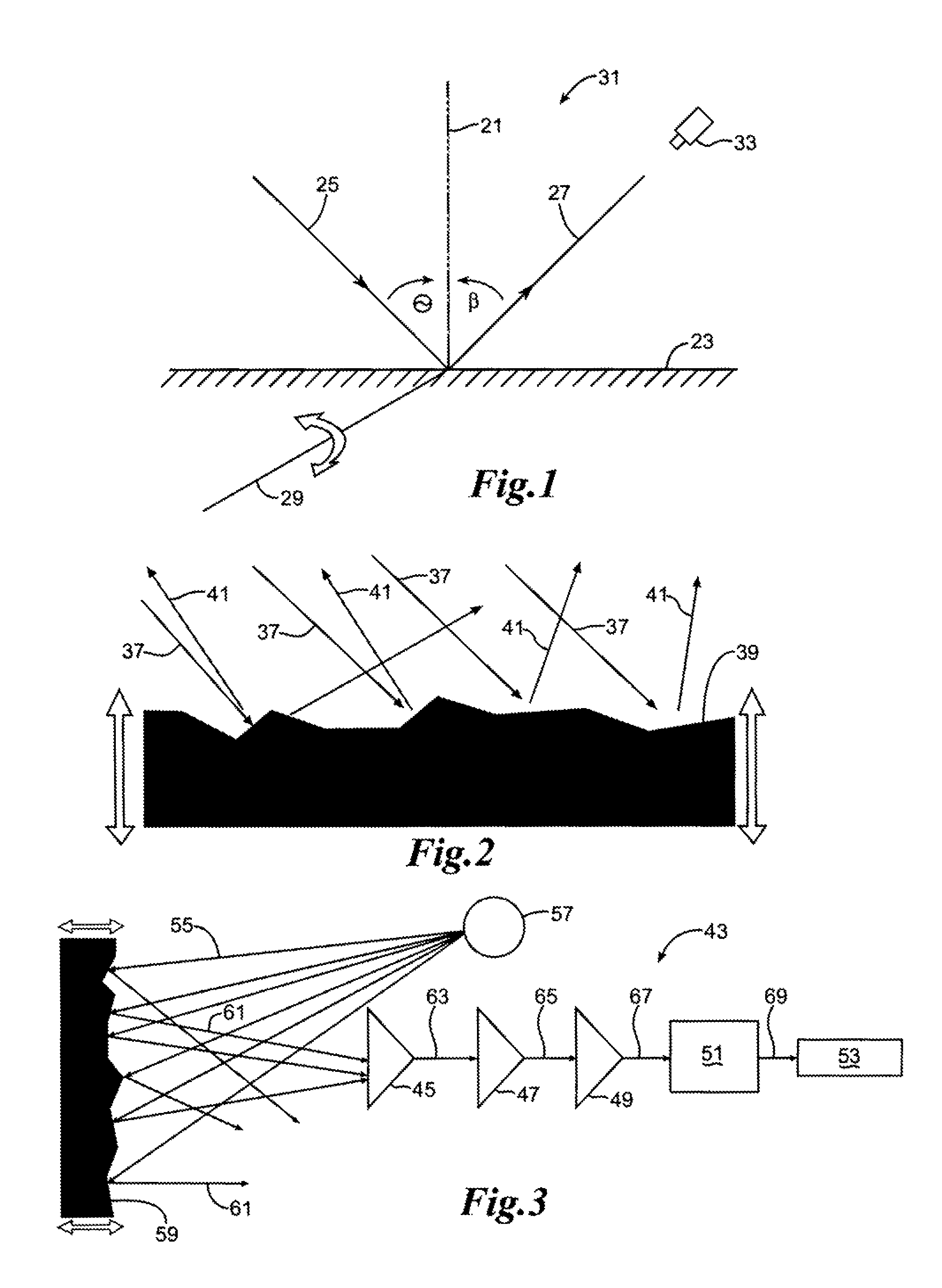
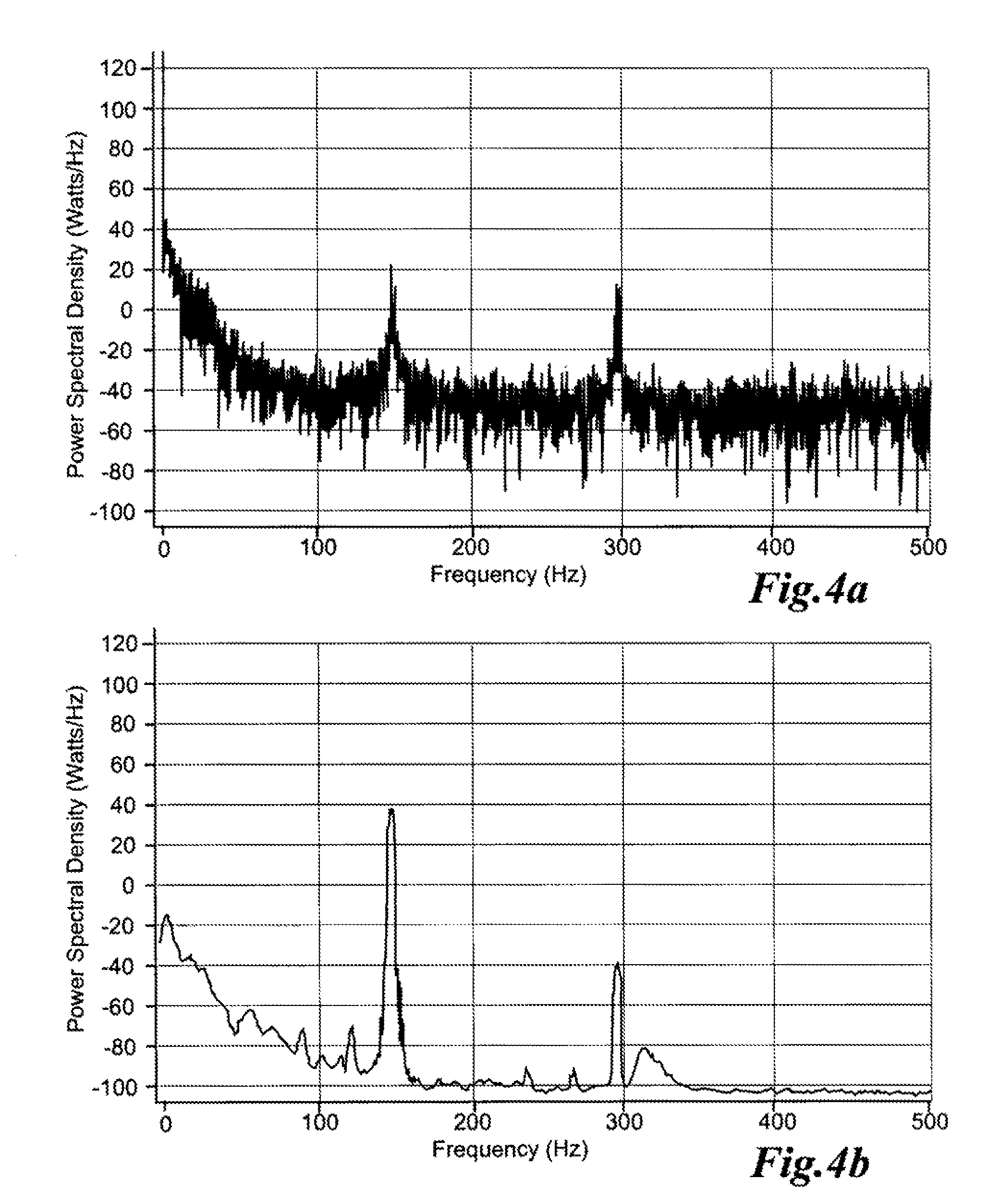
[0019]The present invention senses the hypertemporal images created by modulated light being diffusely reflected from a surface coupled to a source of vibration. The frequency of modulation is contained in the hypertemporal images. The present invention separates...


PUM

PropertyMeasurementUnit
frequencyaaaaaaaaaa
timeaaaaaaaaaa
frequencyaaaaaaaaaa

Abstract

An optical detector senses the intensity of scattered light reflected by a surface coupled to a vibration source. If the vibration source is operating, the coupled surface vibrates at the same frequency. Incident light reflected by the surface is modulated by the vibration at a hypertemporal frequency. The detector produces a direct electrical current as a temporal function of the detected modulated light intensity. A transimpedance amplifier converts the current into a voltage. A voltage amplifier amplifies the voltage. An analog-to-digital converter converts the amplified voltage into digital signal. A digital signal processor converts the digital signal into a function of power spectral density and frequency using Fourier transform and principle component analyses. The vibration signature of the vibration source, if present, is discerned from a graphical display of the foregoing function.

Description

CROSS-REFERENCE TO RELATED APPLICATION[0001]This application is a divisional of U.S. patent application Ser. No. 12 / 636,456 filed on Dec. 11, 2009, now U.S. Pat. No. 8,284,405, which claims the benefit of U.S. Provisional Application No. 61 / 122,702, filed on Dec. 15, 2008, and claims the benefit of the foregoing filing date.STATEMENT OF GOVERNMENT INTEREST[0002]The conditions under which this invention was made are such as to entitle the Government of the United States under paragraph 1(a) of Executive Order 10096, as represented by the Secretary of the Air Force, to the entire right, title and interest therein, including foreign rights.FIELD OF THE INVENTION[0003]The present invention is related to passively detecting a vibration signature by sensing and measuring modulated light diffusely scattered from the surface of a remote object coupled with local vibration of that object. More specifically, the invention analyzes light modulated by a remote surface coupled with either a mech...

Claims


Application Information

Patent Timeline
Patent Type & Authority Patents(United States)
IPC IPC(8): G01N21/55
CPCG01H9/00
Inventor CLARK, FRANK O.
Owner THE UNITED STATES OF AMERICA AS REPRESETNED BY THE SEC OF THE AIR FORCE
Why Eureka
Try Eureka