Large-field unit-magnification catadioptric projection system

a projection system and large-field technology, applied in the field of projection optical systems, can solve the problems of inconvenient embodiment of the above-referenced patents, the design of lenses has not provided the capability of large working distances and diode-laser wavelengths, and the cost of this gain is the substantial reduction of available object/image field siz

Inactive Publication Date: 2013-07-23
COHERENT INC
View PDF26 Cites 2 Cited by
  • Summary
  • Abstract
  • Description
  • Claims
  • Application Information

AI Technical Summary

Problems solved by technology

This provides good access to both the object and image planes but the cost of this gain is the substantial reduction of available object / image field size.
While the projection lens designs described in these above referenced patents are quite suitable for normal photolithography aspects at wavelengths of 404 nanometers (nm), 365 nm and 248 nm and a 0.35 NA exposure system, such lens designs have not provided capabilities at large working distances and diode-laser wavelengths, for example, 808 nm, 980 nm, and 1024 nm.
The design embodiments described in the above-referenced patents are not suitable for exposure systems requiring large rectangular exposure fields with lengths ranging from 100 mm to a few hundred mm, and with working distances of at least 100 mm.

Method used


Image

  • Large-field unit-magnification catadioptric projection system
  • Large-field unit-magnification catadioptric projection system
  • Large-field unit-magnification catadioptric projection system

Examples


Embodiment Construction

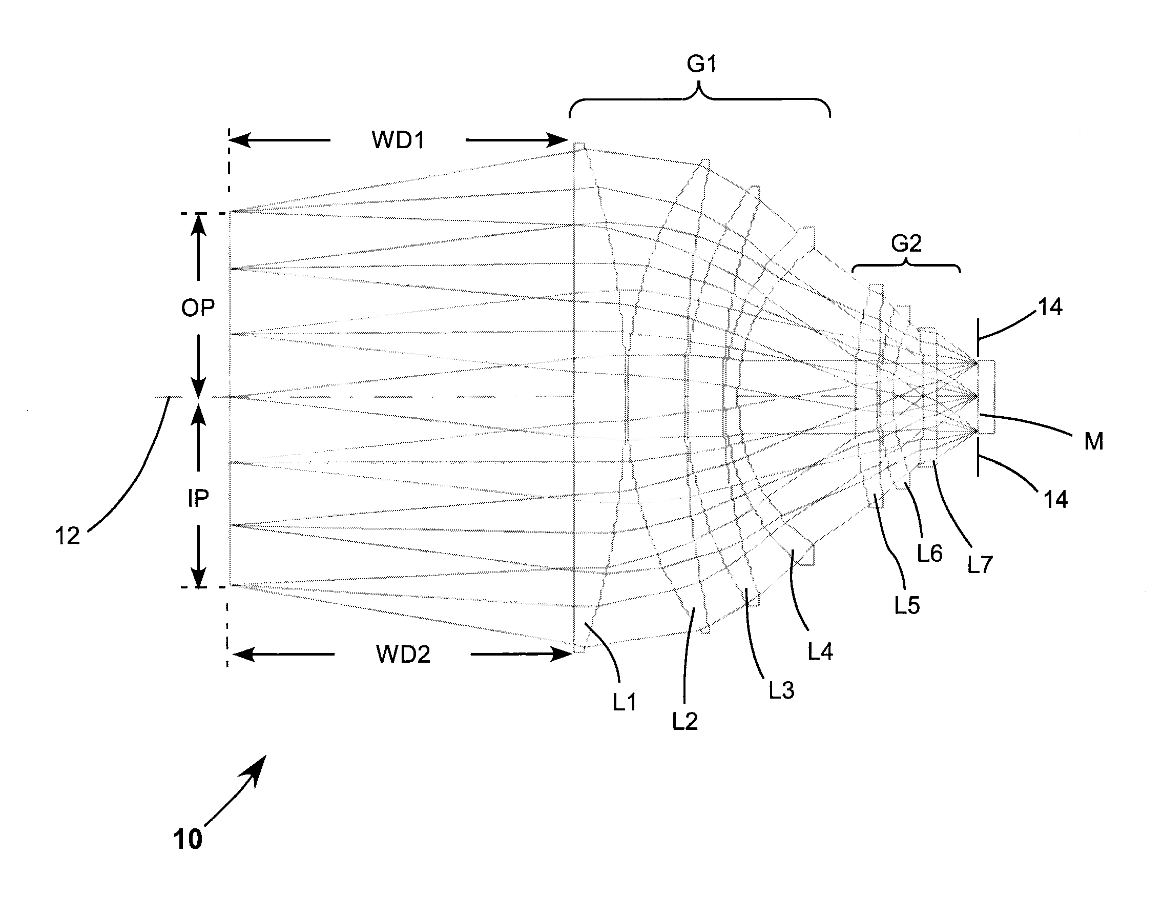
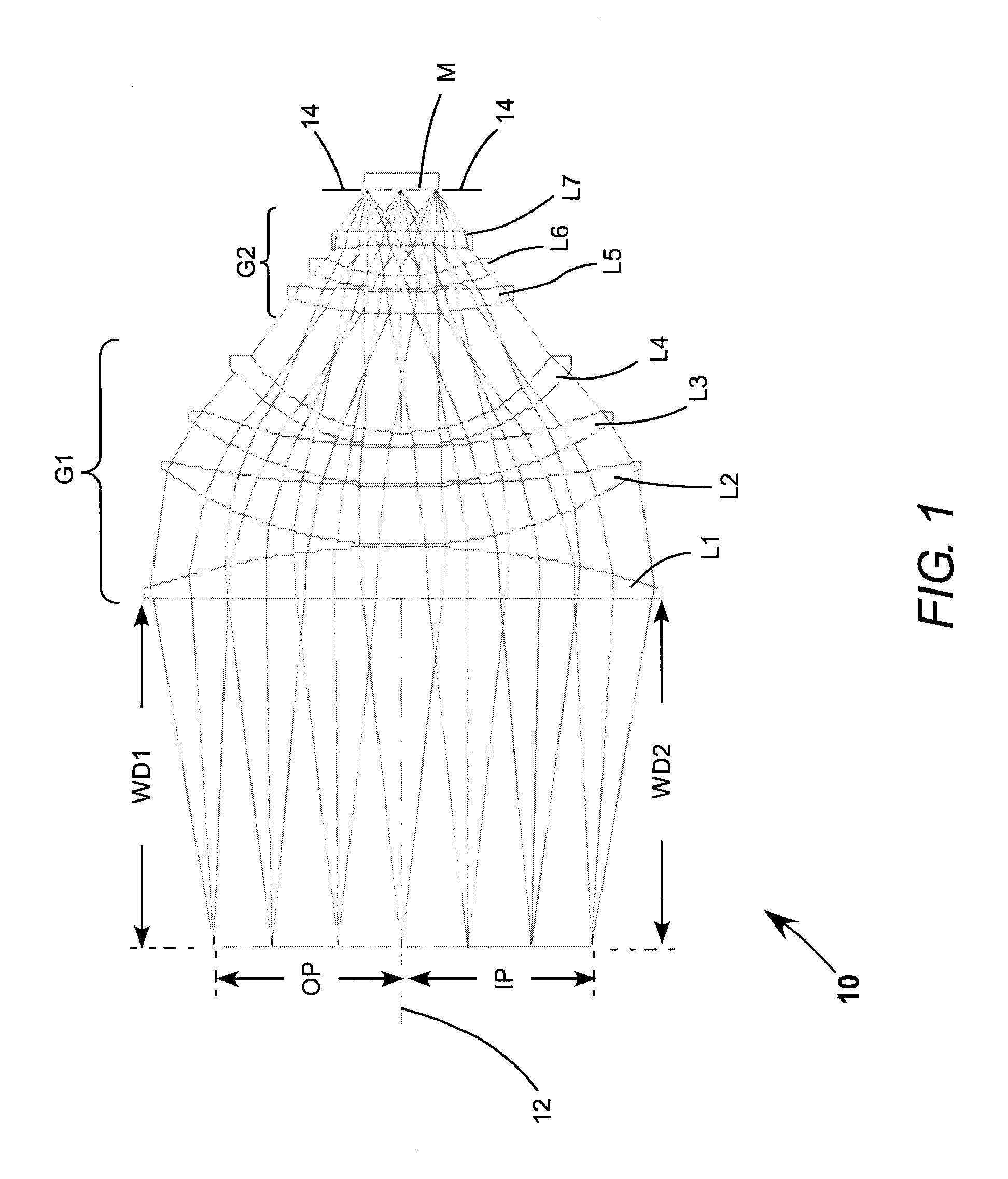
[0037]Referring now to the drawings, wherein like components are designated by like reference numerals, FIG. 1 schematically illustrates a first preferred embodiment 10 of a unit-magnification projection optical system in accordance with the present invention. System 10 has a longitudinal optical axis 12. Arranged along axis 12 are an object plane OP, and an image plane IP, a lens group G1 having net negative optical power, a lens group G2 having net positive optical power, and a concave mirror M. An aperture stop 14, which can be a variable aperture stop, is located at mirror M. In the embodiment of FIG. 1 positive lens group G1, negative lens group G2, and mirror M are air-spaced apart from each other, while object plane OP and image plane IP are in the same plane, or coplanar.

[0038]In the embodiment of FIG. 1, lens group G1 includes air-spaced lens elements L1, L2, L3, and L4. L1 is a plano-convex element and L2 is a positive meniscus element. L3 is a positive meniscus element; a...


PUM


Abstract

A unit magnification projection optical system includes, listed in order along a system axis, a mirror, a lens group having negative power and a lens group having positive power. The optical system is a symmetric system, with an object plane on one side of the system axis and an object plane on an opposite side of the system axis. The object and image planes are spaced apart from the positive lens group by a working distance greater than 100 millimeters.

Description

PRIORITY CLAIM[0001]This application claims priority of U.S. Provisional Application No. 61 / 381,718, filed Sep. 10, 2010 and U.S. Provisional Application No. 61 / 390,502 filed Oct. 6, 2010, both assigned to the assignee of the present invention and the complete disclosure of which is hereby incorporated herein by reference.TECHNICAL FIELD OF THE INVENTION[0002]The present invention relates in general to projection optical systems. The invention relates in particular to large-field, unit-magnification projection optical systems for photolithography and masked laser-patterning applications.DISCUSSION OF BACKGROUND ART[0003]Photolithography is presently employed in sub-micron resolution integrated circuit (IC) manufacturing, and, to an increasing degree, in advanced, wafer-level IC packaging technologies, and in micro-mechanical systems (MEMS), nano-technology, among other applications. These applications require multiple imaging capabilities ranging from relatively low resolution, for ...

Claims


Application Information

Patent Timeline
Patent Type & Authority Patents(United States)
IPC IPC(8): G02B17/00
CPCG02B17/0892G03F7/70225
Inventor MERCADO, ROMEO I.
Owner COHERENT INC
Why Eureka
Try Eureka