Toneable conduit with heat treated tone wire

a tone wire and conduit technology, applied in the field of toneable conduits, can solve problems such as potential drawbacks in the storage of toneable conduits, and achieve the effect of reducing the risk of re-use and re-us

Inactive Publication Date: 2013-07-30
DURA LINE CORP A CORP OF KY
View PDF51 Cites 14 Cited by
  • Summary
  • Abstract
  • Description
  • Claims
  • Application Information

AI Technical Summary

Benefits of technology

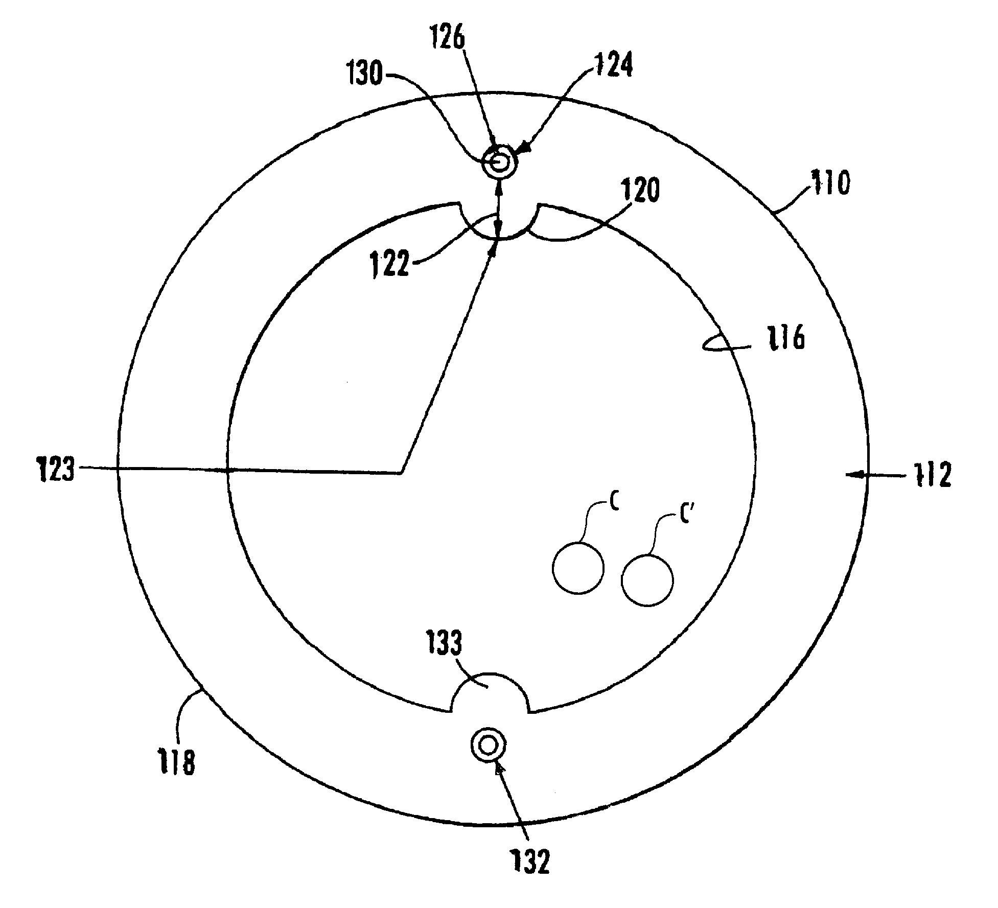
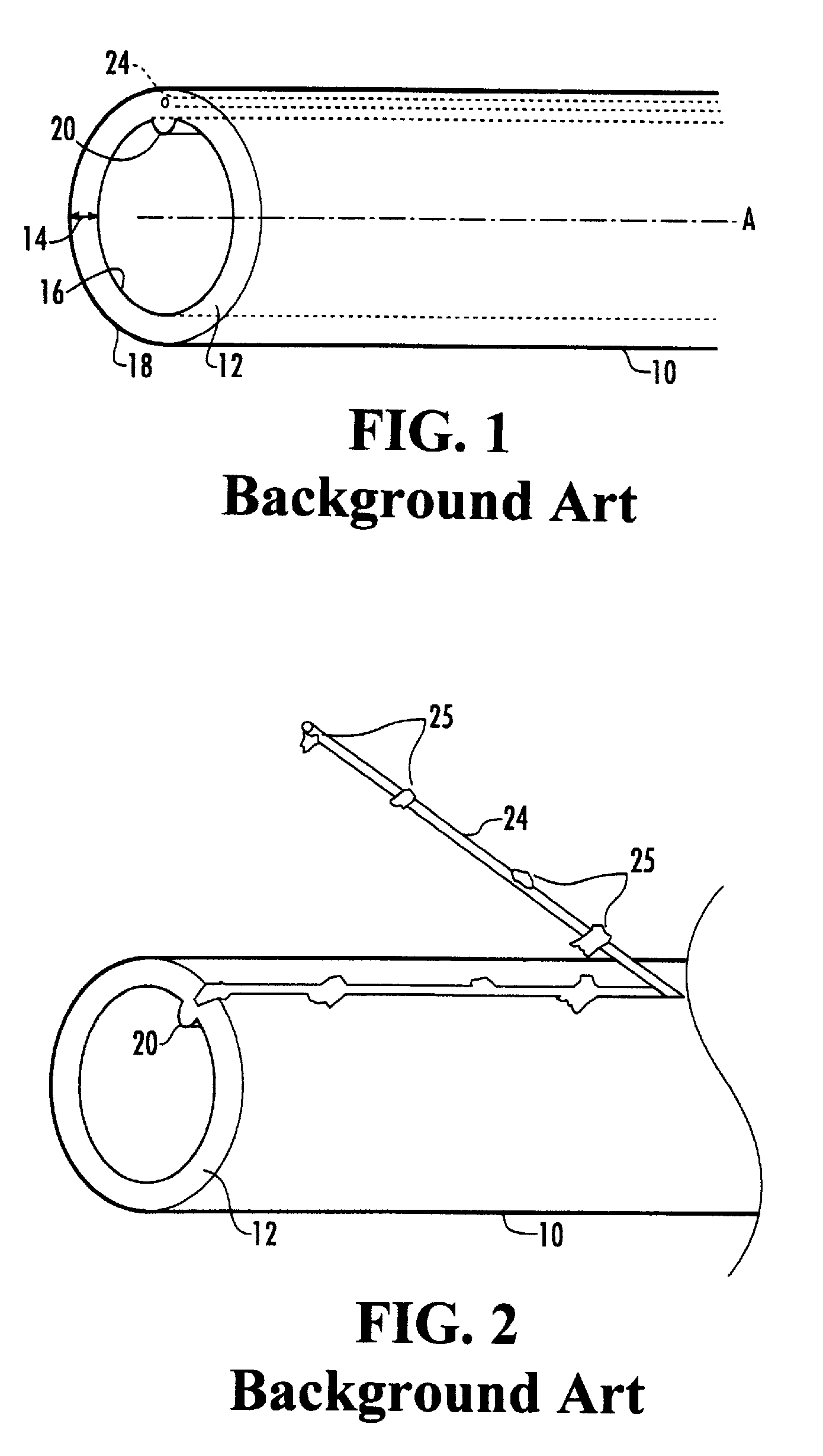
[0013]Applicants' invention in the background art of FIG. 1 solved several problems of the prior art. For example, the wire 24 could be pulled though the sidewall 12 to permit easy coupling with another conduit or fitting. Further, the non-stick coating described in conjunction with the wire 24 of FIG. 1 allows the wire 24 to be pulled through the sidewall 12 of the conduit 10 without having portions 25 (FIG. 2) of the sidewall 12 adhered to the wire 24. In other words, the nonstick coating of the background art prevents the situation depicted in FIG. 2, wherein the conduit's sidewall 12 would be damaged as the toning signal wire 24 is pulled through it, such that leaks would be more likely to occur.

Problems solved by technology

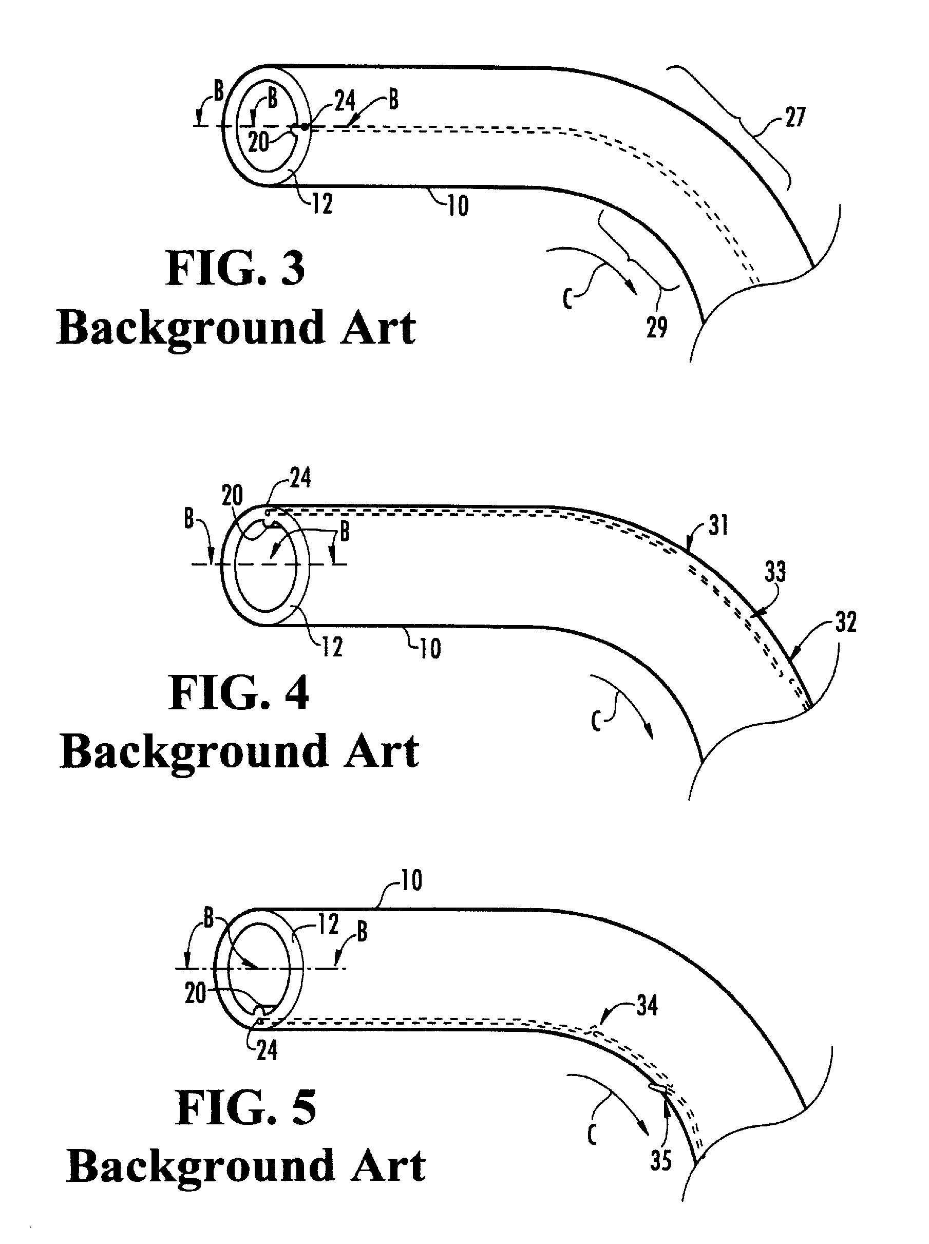
Moreover, tension placed on the polymeric tube of the conduit 10 which causes elastic deformation in the vicinity of the channel holding the wire 24, causes the channel to clamp down on and hold the wire 24 very tightly, in the same fashion as the common toy known as “Chinese handcuffs.” This characteristic of the conduit 10 can lead to a drawback under certain circumstances.
For example, a potential drawback could occur in the storage of the toneable conduit 10.

Method used


Image

  • Toneable conduit with heat treated tone wire
  • Toneable conduit with heat treated tone wire
  • Toneable conduit with heat treated tone wire

Examples


Embodiment Construction

[0042]The present invention now is described more fully hereinafter with reference to the accompanying drawings, in which embodiments of the invention are shown. This invention may, however, be embodied in many different forms and should not be construed as limited to the embodiments set forth herein; rather, these embodiments are provided so that this disclosure will be thorough and complete, and will fully convey the scope of the invention to those skilled in the art.

[0043]Like numbers refer to like elements throughout. In the figures, the thickness of certain lines, layers, components, elements or features may be exaggerated for clarity. Broken lines illustrate optional features or operations unless specified otherwise.

[0044]The terminology used herein is for the purpose of describing particular embodiments only and is not intended to be limiting of the invention. Unless otherwise defined, all terms (including technical and scientific terms) used herein have the same meaning as c...


PUM

PropertyMeasurementUnit
lengthaaaaaaaaaa
elongationsaaaaaaaaaa

Abstract

A toneable conduit includes an elongate polymeric tube having a sidewall with an interior surface and an exterior surface. The interior surface defines a main channel for holding communication or power cables. A sub-channel extends longitudinally between the exterior and interior surfaces of the tube. An electrically continuous, toning signal wire is located within the sub-channel. The toning signal wire is formed of an annealed metal or metals and is capable of elongation to a certain extent without breakage, wherein the certain extent approximates or exceeds the extent of elongation of the tube at the point of failure.

Description

CROSS REFERENCE TO RELATED APPLICATIONS[0001]This application is a continuation-in-part of, U.S. patent application Ser. No. 10 / 830,754, filed Apr. 23, 2004, now U.S. Pat No. 7,820,090 which is a continuation of U.S. patent application Ser. No. 10 / 158,810, filed May 30, 2002 (now abandoned), which is a continuation-in-part of U.S. patent application Ser. No. 09 / 989,289, filed Nov. 20, 2001 (now U.S. Pat. 7,361,835). The entire contents of the three priority applications are herein incorporated by reference.FIELD OF THE INVENTION[0002]The present invention relates to toneable conduit and more particularly to toneable conduit that can be detected by conventional toning equipment and that includes a wire that is capable of being torn out of the conduit to allow the conduit and wire to be coupled.BACKGROUND OF THE INVENTION[0003]Conduit is often buried to provide an underground path for cables such as coaxial cables and fiber optic cables. In particular, conduit is typically formed of a...

Claims


Application Information

Patent Timeline
Patent Type & Authority Patents(United States)
IPC IPC(8): H02G3/04B29C48/09
CPCB29C47/025F16L1/11F16L9/125F16L25/01G02B6/447H02G3/0481H02G3/06H02G9/06B29C47/0023B29C47/0004B29C66/1224B29C47/0026B29C47/003B29C47/064B29C47/225B29C47/26B29C47/28B29C47/34B29C47/8815B29C65/48B29C66/5221B29C66/52292B29K2023/06B29K2023/065B29K2027/06B29K2027/18B29K2705/00B29K2995/0005B29L2022/00B29L2031/707G02B6/4459H02G2200/20B29C66/1222B29C48/022B29C48/06B29C48/09B29C48/10B29C48/12B29C48/154B29C48/19B29C48/20B29C48/327B29C48/335B29C48/34B29C48/355B29C48/911B29C48/919G02B6/562
Inventor MORROW, JASON
Owner DURA LINE CORP A CORP OF KY
Why Eureka
Try Eureka