Magnetoresistive sensors having an improved free layer

a magnetoresistive sensor and free layer technology, applied in the field of magnetoresistive transducers, can solve the problems of high gilbert damping constant and magnetic noise induced, and achieve the effects of low gilbert damping constant, reduced overall thickness, and high magnetization

Active Publication Date: 2013-07-30
WESTERN DIGITAL TECH INC
View PDF72 Cites 158 Cited by
  • Summary
  • Abstract
  • Description
  • Claims
  • Application Information

AI Technical Summary

Benefits of technology

[0004]Various embodiments of the subject disclosure overcome the foregoing limitations by providing an improved multilayered FL structure comprising a first magnetic layer having a positive spin polarization and a positive magnetostriction and a second, counteracting, magnetic layer having a negative magnetostriction and also having relatively high magnetization (e.g., greater than 600 emu / cm3) and a low Gilbert damping constant (e.g., less than 0.02). In certain embodiments, the second magnetic layer is an alloy comprising cobalt (Co) and boron (B). In some embodiments, the first magnetic layer comprises a material, e.g., an alloy of cobalt and iron (CoFe), having a polycrystalline structure. Such an improved multilayered FL can have a reduced overall thickness as compared to conventional FLs which use NiFe as a second magnetic layer, thereby helping to reduce the total thickness of the sensor stack, and providing a lower Gilbert damping constant, which helps to reduce a magnetic noise for the TMR sensor.

Problems solved by technology

In addition, Ni-rich NiFe alloys have a high Gilbert damping constant, which contributes to a magnetic noise induced by a vibration of grain structures.

Method used


Image

  • Magnetoresistive sensors having an improved free layer
  • Magnetoresistive sensors having an improved free layer
  • Magnetoresistive sensors having an improved free layer

Examples


Embodiment Construction

[0015]In the following detailed description, numerous specific details are set forth to provide a full understanding of the present invention. It will be apparent, however, to one ordinarily skilled in the art that the present invention may be practiced without some of these specific details. In other instances, well-known structures and techniques have not been shown in detail to avoid unnecessarily obscuring the present invention.

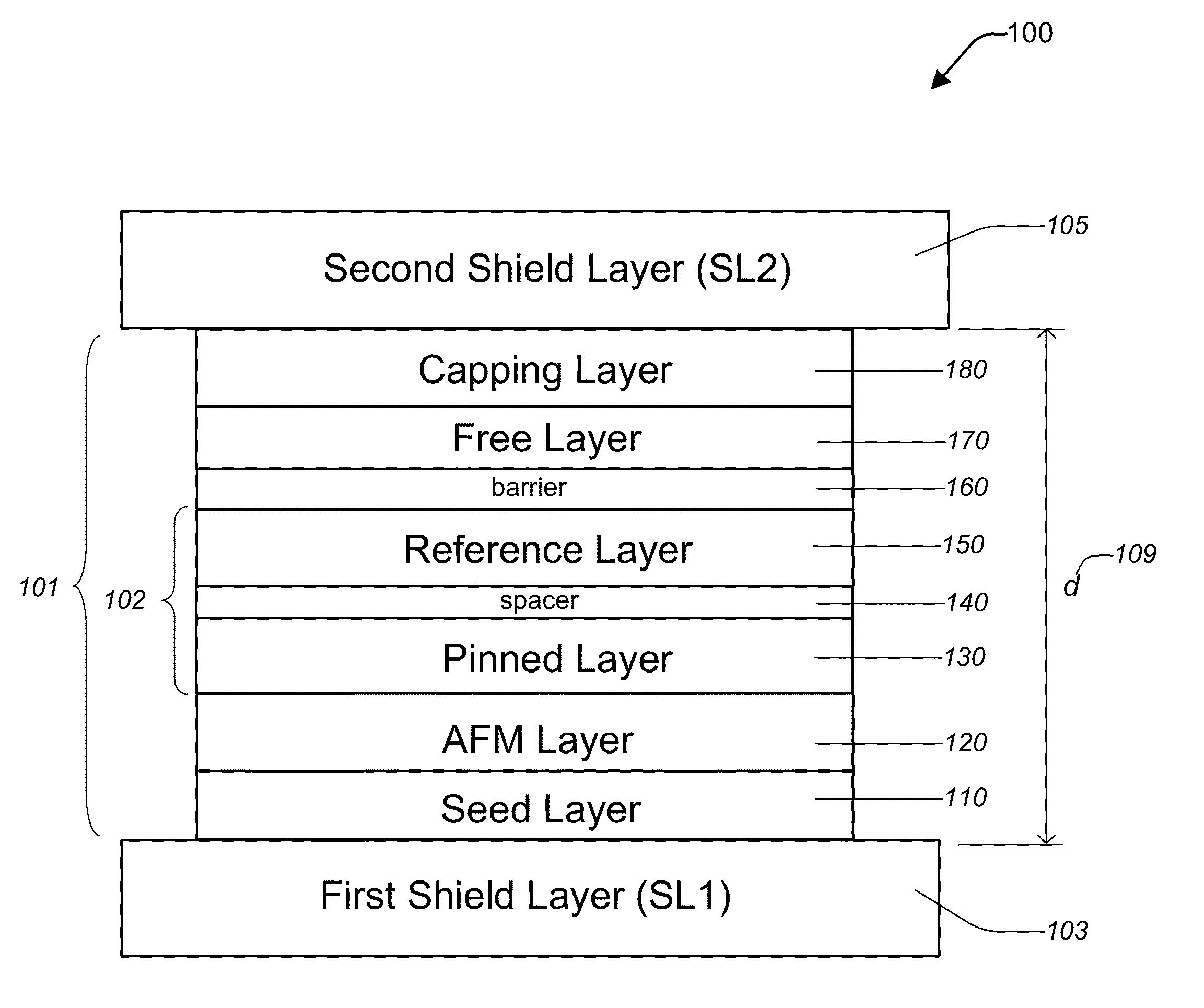
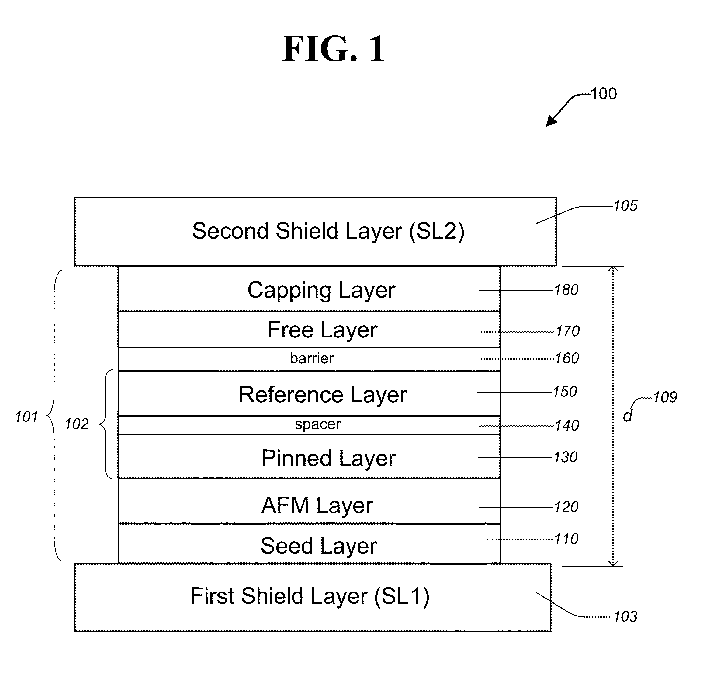
[0016]FIG. 1 is a diagram depicting a TMR element 100 according to one aspect of the subject disclosure. The TMR element 100 includes a sensor stack 101 disposed between a first (bottom) shield layer (SL1) 103 and a second (top) shield layer (SL2) 105 and having a shield-to-shield distance (d) 109. For simplicity, FIG. 1 is not drawn to scale. The sensor stack 101 includes a seed layer 110 disposed over the SL1103, a pinning or anti-ferromagnetic (AFM) layer 120 disposed over the seed layer 120, a bottom electrode 102 disposed over the AFM layer 120, a tu...


PUM

PropertyMeasurementUnit
thicknessaaaaaaaaaa
thicknessaaaaaaaaaa
thicknessaaaaaaaaaa

Abstract

A magnetoresistive sensor having a novel free layer and a method of producing the same are disclosed. The magnetoresistive sensor comprises a pinned layer, a barrier layer disposed over the pinned layer, and a free layer disposed over the barrier layer. The free layer comprises a first magnetic layer disposed over the barrier layer. The first magnetic layer has a positive spin polarization, a positive magnetostriction, and a polycrystalline structure. The free layer further comprises a second magnetic layer disposed over the first magnetic layer. The second magnetic layer has a negative magnetostriction and comprises at least cobalt (Co) and boron (B).

Description

FIELD OF THE INVENTION[0001]The present invention generally relates to magnetic transducers and, in particular, relates to magnetoresistive sensors having an improved free layer.BACKGROUND OF THE INVENTION[0002]Tunnel magnetoresistance (TMR) sensors are frequently employed as magnetoresistive sensors in the magnetic heads of hard disk drives. As the areal density of hard disks approaches 1 Tb / in2, it is desirable to reduce the magnetic reader gap spacing to about 25 nm or below. To do so will require a thinner TMR sensor stack, however. Many readers have a free layer (FL) about 60-80 nm in thickness, in order to achieve high TMR ratio (dR / R) and lower magnetostriction. This FL design involves a thin first magnetic layer acting as an interface layer that has a high spin polarization and a high positive magnetostriction. To counteract the high positive magnetostriction of the first magnetic layer and achieve a desired net low magnetostriction (e.g., below 2×10⁻⁶) for the FL, a second,...

Claims


Application Information

Patent Timeline
Patent Type & Authority Patents(United States)
IPC IPC(8): G11B5/127
CPCG01R33/093G11B5/3909G11B5/3912
Inventor LENG, QUNWENKAISER, CHRISTIANGUO, YIMINPAKALA, MAHENDRAMAO, SINING
Owner WESTERN DIGITAL TECH INC
Why Eureka
Try Eureka