ESD protection circuit

a protection circuit and circuit technology, applied in the direction of overvoltage protection resistors, emergency protection arrangements for limiting excess voltage/current, overvoltage protection resistors, etc., can solve the problem of gate leakage current, severe, etc., and achieve safe discharging of esd phenomena and amplifying equivalent capacitance

Inactive Publication Date: 2013-07-30
NAT SUN YAT SEN UNIV
View PDF2 Cites 15 Cited by
  • Summary
  • Abstract
  • Description
  • Claims
  • Application Information

AI Technical Summary

Benefits of technology

[0003]The primary object of the present invention is to provide an ESD protection circuit including a silicon controlled rectifier, a first CMOS inverter, a first transistor, a current mirror, a PMOS capacitor and a resistor. The first CMOS inverter electrically connects with the silicon controlled rectifier. The first transistor comprises a first end, a second end and a third end, wherein the first end electrically connects with the silicon controlled rectifier and the first CMOS inverter, and the current minor electrically connects with the third end of the first transistor. The PMOS capacitor electrically connects with the current mirror. The resistor electrically connects with the first CMOS inverter, the second end of the first transistor and the PMOS capacitor. By integrating the current minor with the first transistor, when an electrostatic discharge (ESD) phenomenon occurs in the ESD protection circuit, the first transistor operates in a conduction state so as to amplify the equivalent capacitance produced from the current minor. Therefore, sufficient RC constant ensures that the first CMOS inverter does not shut down too soon. Also, sufficient RC constant makes the silicon controlled rectifier maintained in a conduction state to lastingly provide an electrostatic discharge path for safely discharging ESD phenomena. The present invention utilizes the first transistor acted as a control switch and the capacitance amplification feature of the current minor, therefore, a chip layout area and a leakage current for the ESD protection circuit of the present invention can be effectively reduced.

Problems solved by technology

However, with advanced process in semiconductor industry entering a nanoscale era, the gate oxide layer of the MOS device in nanoscale CMOS technology gradually becomes thinner and thinner, which results in severe gate leakage current of the MOS device caused by gate tunneling effect so as to make relative circuits perform a failed operation.

Method used


Image

  • ESD protection circuit
  • ESD protection circuit
  • ESD protection circuit

Examples


Embodiment Construction

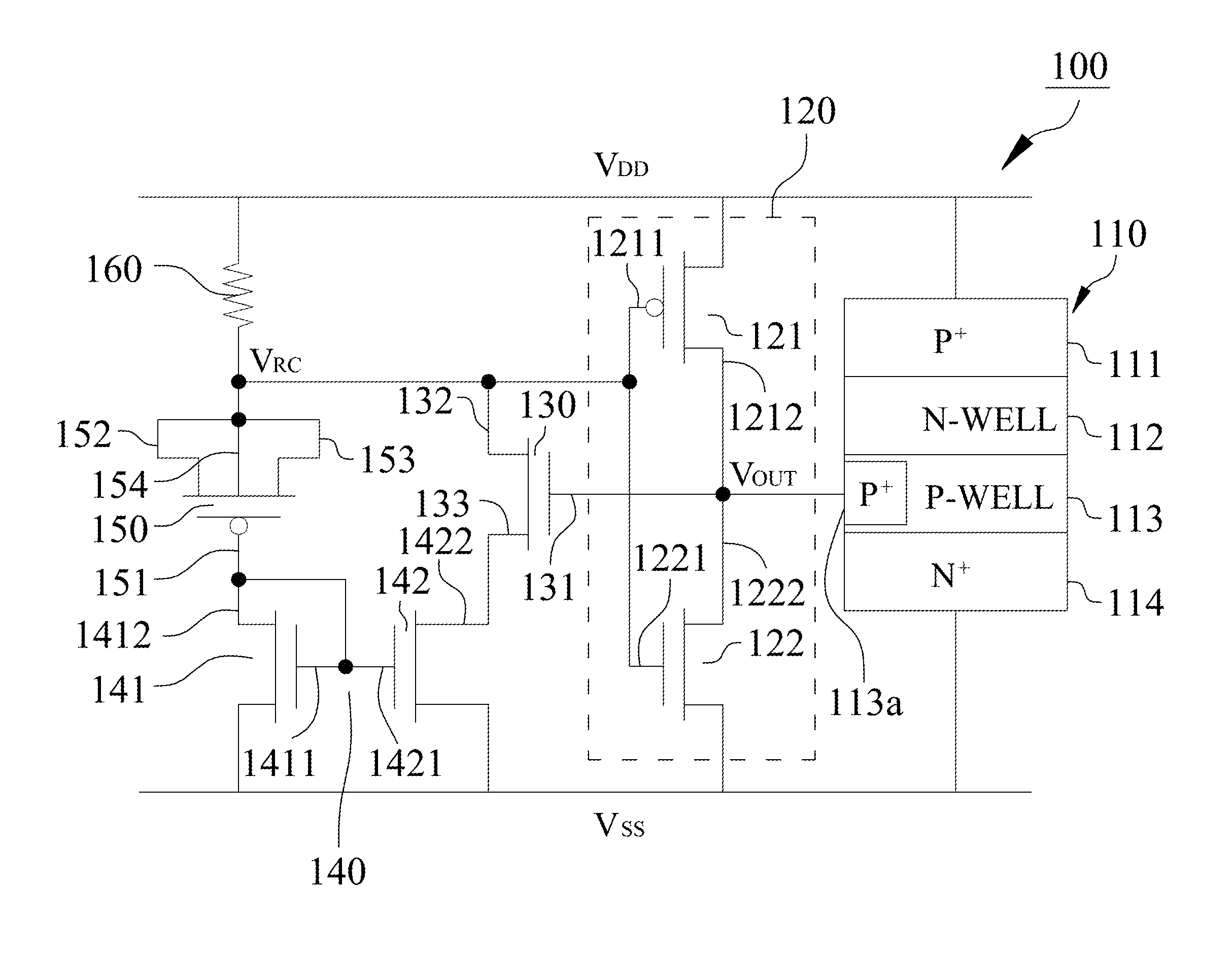
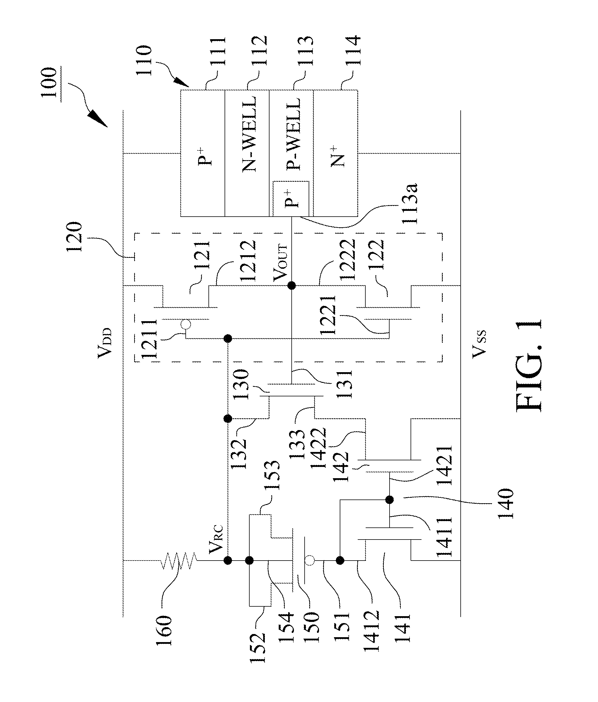
[0010]With reference to FIG. 1, an ESD protection circuit 100 in accordance with a first embodiment of the present invention includes a silicon controlled rectifier 110, a first CMOS inverter 120, a first transistor 130, a current mirror 140, a PMOS capacitor 150 and a resistor 160, wherein the first CMOS inverter 120 electrically connects with the silicon controlled rectifier 110. The first transistor 130 comprises a first end 131, a second end 132 and a third end 133, wherein the first end 131 electrically connects with the silicon controlled rectifier 110 and the first CMOS inverter 120, and the current mirror 140 electrically connects with the third end 133 of the first transistor 130. The PMOS capacitor 150 comprises a fourth end 151, a fifth end 152 and a sixth end 153, the fourth end 151 of the PMOS capacitor 150 electrically connects with the current mirror 140, and the resistor 160 electrically connects with the first CMOS inverter 120, the second end 132 of the first trans...


PUM


Abstract

An ESD protection circuit with leakage current reduction function includes a silicon controlled rectifier, a first CMOS inverter, a first transistor, a current mirror, a PMOS capacitor and a resistor. The first CMOS inverter electrically connects with the silicon controlled rectifier. The first transistor comprises a first end, a second end and a third end, wherein the first end electrically connects with the silicon controlled rectifier and the first CMOS inverter, and the current mirror electrically connects with the third end of the first transistor. The PMOS capacitor electrically connects with the current mirror, and the resistor electrically connects with the first CMOS inverter, the second end of the first transistor and the PMOS capacitor.

Description

FIELD OF THE INVENTION[0001]The present invention is generally related to an ESD protection circuit, which particularly relates to the ESD protection circuit with smaller layout area and leakage current reduction functions.BACKGROUND OF THE INVENTION[0002]A conventional ESD protection circuit 200 as illustrated in FIG. 6 includes an RC circuit 210, a CMOS inverter 220 electrically connected with the RC circuit 210, and a silicon controlled rectifier 230 electrically connected with the CMOS inverter 220. A traditional ESD detection can be achieved through combination of the RC circuit 210 and MOS capacitors owning to the reason that MOS capacitors possess the largest capacitance per unit area in the CMOS processes. However, with advanced process in semiconductor industry entering a nanoscale era, the gate oxide layer of the MOS device in nanoscale CMOS technology gradually becomes thinner and thinner, which results in severe gate leakage current of the MOS device caused by gate tunne...

Claims


Application Information

Patent Timeline
Patent Type & Authority Patents(United States)
IPC IPC(8): H02H9/00H02H1/00H01C7/12H02H1/04H02H3/22
CPCH02H9/046
Inventor ALTOLAGUIRRE, FEDERICO A.KER, MING-DOUWANG, CHUA-CHIN
Owner NAT SUN YAT SEN UNIV
Why Eureka
Try Eureka