Manufacture of split tip catheters

a technology of split tip and catheter, which is applied in the field of catheter, can solve the problems of reducing efficiency, reducing the duration of treatment needed for adequate dialysis, and effectively reducing dialysis efficiency through recirculation, so as to reduce the thickness of the septum, shorten the manufacturing time, and simplify the process

Active Publication Date: 2013-08-06
BARD ACCESS SYST
View PDF658 Cites 44 Cited by
  • Summary
  • Abstract
  • Description
  • Claims
  • Application Information

AI Technical Summary

Benefits of technology

[0021]The present invention is advantageous, among other reasons, because only one distal tip segment is bonded to the catheter body (in contrast to prior art where two tip segments must be bonded), thus simplifying the process and shortening the manufacturing time. A further advantage is that bonding a single distal tip segment permits reduced septum thickness in the catheter body (and therefore increased luminal cross-sections) since the septum does not have to accommodate the attachment of two separate distal end tubes.

Problems solved by technology

However, conditions such as access recirculation decrease efficiency.
Excess recirculation effectively reduces dialysis efficiency and lengthens the duration of the treatment needed for adequate dialysis.
Access recirculation can be particularly of concern when using a double lumen catheter due to the close proximity of the intake and outflow ports at the distal tip of the catheter.
However, certain disadvantages have been noted by such large longitudinal spacing between the distal ends of the respective lumens.
For example, blood flow stagnation in the region of the blood vessel between two widely separated tips can lead to clot formation.
However, such geometric differences are difficult to incorporate into split-tip catheters using conventional manufacturing techniques.

Method used


Image

  • Manufacture of split tip catheters
  • Manufacture of split tip catheters
  • Manufacture of split tip catheters

Examples


Embodiment Construction

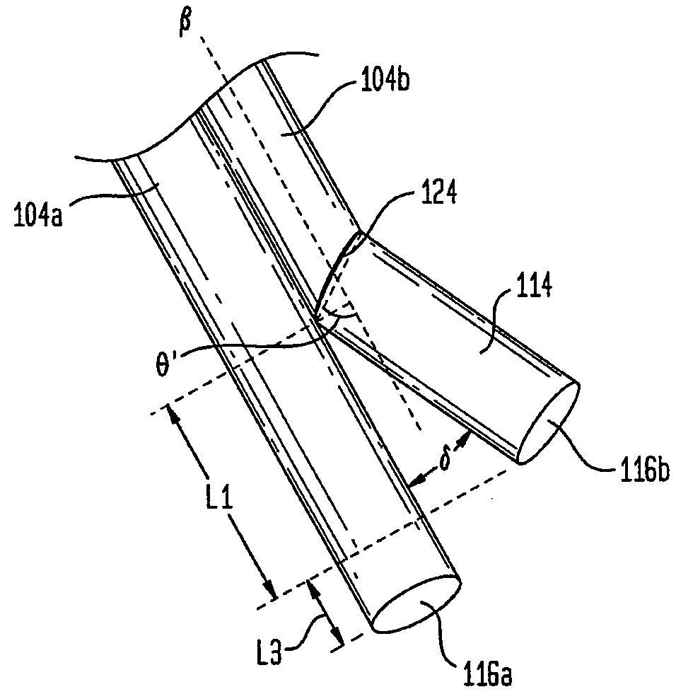
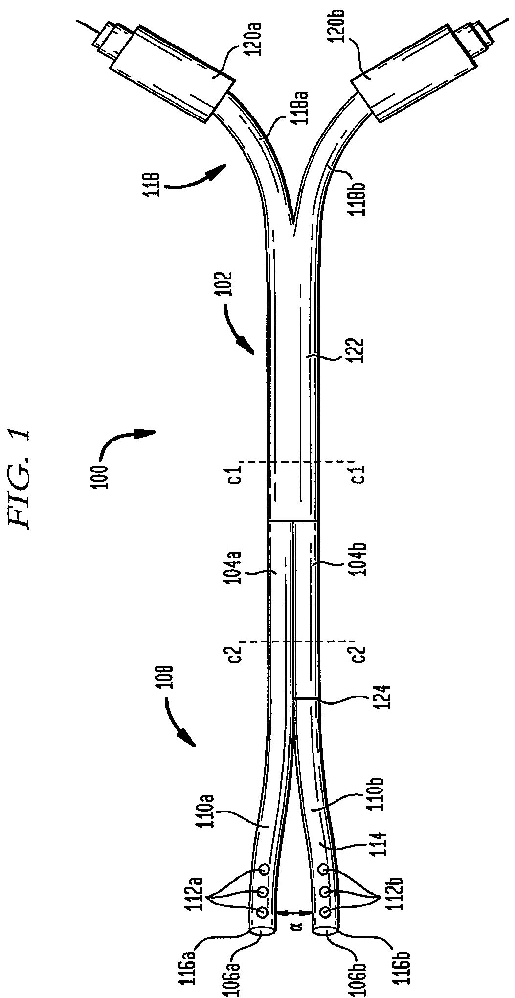
[0060]In FIG. 1 an embodiment of a split tip catheter 100 according to the invention is shown having a catheter body 102 with two internal lumens 104a, 104b (collectively, the lumens 104). The lumens 104 include respective inner lumen pathways 106a, 106b (collectively, the pathways 106) extending longitudinally through the catheter body 102. The catheter body 102 has a split-tip distal end 108 in which the catheter body 102 (and the lumens 104) separate into two distal lumen tip segments, 110a, 110b (collectively, the lumen tips 110). One of the lumens 104b has been trimmed to a length less than the other lumen 104a. A lumen tip segment 114 has been joined to the trimmed lumen 104b such that the lumen tip 110b includes the lumen tip segment 114 and such that the lumen tip segment 114 is in fluid communication with the trimmed lumen 104b. The lumen tip 110b forms an angle α with respect to the other lumen tip 110a. The value of α can be zero or non-zero and is preferably in the range...


PUM

PropertyMeasurementUnit
timeaaaaaaaaaa
timeaaaaaaaaaa
timeaaaaaaaaaa

Abstract

Multi-lumen catheter devices having at least one split-tipped end are disclosed, together with methods of forming such split tip catheters. In one aspect of the invention, the manufacturing methods can include the steps of: providing a catheter body having at least a first and a second internal lumen extending longitudinally through the catheter body; removing a distal portion of the catheter body to form a first distal tip segment such that the first lumen extends longitudinally within this tip segment beyond the second lumen; and joining a second lumen tip segment to the catheter body in communication with the second lumen. The second tip segment can be joined to the catheter body such that it is at least partially separated from the first tip segment and, in some embodiments, preferably diverges at an angle relative to the first tip segment.

Description

CROSS REFERENCE TO RELATED APPLICATIONS[0001]This application claims the benefit of priority to U.S. Provisional Application No. 60 / 980,633, filed Oct. 17, 2007, and titled “Manufacture of Split Tip Catheters,” which is incorporated by reference in its entirety herein. The following three applications, filed concurrently herewith, are related to the subject matter of this application and are incorporated by reference in their entirety herein: 1) U.S. patent application Ser. No. 12 / 244,554, titled “Catheters With Enlarged Arterial Lumens,” and published as US 2009 / 0204079; 2) U.S. patent application Ser. No. 12 / 244,544, titled “Fusion Manufacture of Multi-Lumen Catheters,” and published as US 2009 / 0209940; and 3) U.S. patent application Ser. No. 12 / 244,559, titled “Manufacture of Fixed Tip Catheters,” and published as US 2009 / 0205189.BACKGROUND[0002]The present invention generally relates to catheters and preferably to multi-lumen catheters used for vascular access.[0003]Multi-lumen ...

Claims


Application Information

Patent Timeline
Patent Type & Authority Patents(United States)
IPC IPC(8): B29C65/02B32B38/00B32B37/00
CPCA61M25/001A61M25/0032A61M25/0068A61M25/0069A61M25/0009A61M25/0026Y10T29/49888A61M25/007A61M25/0074A61M25/008A61M2025/0031A61M2025/0034A61M2025/0188Y10T29/49826Y10T156/1064Y10T156/1082A61M25/003A61M25/0194A61M25/0067A61M2025/0004A61M25/0043A61M25/0021
Inventor NIMKAR, SHEKHAR D.DUFRESNE, SR., CHRISTIANTOBIN, ERIC
Owner BARD ACCESS SYST
Why Eureka
Try Eureka