System for scheduling battery charge and discharge in a reconfigurable battery

a battery and reconfigurable technology, applied in the field of system for scheduling battery charge and discharge, can solve the problems of significant overhead, not even damaging the cell itself, and explosion, and achieve the effects of increasing workload, excellent performance, and large voltage drop

Active Publication Date: 2013-08-13
RGT UNIV OF MICHIGAN
View PDF13 Cites 66 Cited by
  • Summary
  • Abstract
  • Description
  • Claims
  • Application Information

AI Technical Summary

Benefits of technology

[0106]kRR effectively adapts itself to different workloads developed in 4 phases. For workloads lighter than 1 C×T (Phase 1 in the figure), kRR acts as 1RR which is most effective. Thus, compared to nRR, suggests that at a very low discharge rate, electrochemical dynamics inside the cell are inefficient in converting chemical energy to electrical energy although the effect is subject to individual cell characteristics. Compared to 1+1RR, 1RR is found to perform better at a low discharge rate, showing a 13% performance gain. As the workload gets heavier, however, 1RR loses its performance since the recovery efficiency lags behind the discharge rate. In Phase 2, kRR's performance is excellent, because kRR effectively determines the right number of parallel-connected cells to accommodate the increasing workload while attempting to make best of their recovery efficiency. As a result, kRR outperforms 1RR and 1=1RR by up to 11% and 21%, respectively, and achieves a reasonable gain of 1.4% against nRR. In Phase 3, kRR's scheduling performance is, on average, as good as nRR's. In other words, as few parallel-connected cells as 4 are insufficient for kRR to exploit v. As the workload becomes even heavier (Phase 4), more parallel-connected cells are required since not enough time is spend in offsetting a significant voltage drop. Obviously, such a large voltage drop can be handled by using more parallel-connected cells. Thus, kRR acts as nRR. kRR maximizes the battery usability by scheduling the charge, discharge, and rest activities while adapting itself to the varying workloads.
[0107]δG is a threshold according to which parallel-connected cells are partitioned into GH and GL. The cells whose SoC level is below δG are put into GL. This classification is to prevent the cells from suffering the entire terminal voltage drop of the battery pack due mainly to instantaneous high loads at their low SoC level. Moreover, GL serves as a buffer in which the charge is reserved and then delivered to accommodate light loads. The size of the buffer, however, should be adjusted to the load; the higher the load, the larger the value of 6G. The dynamic adaptation of δG supports the schedulability and hence extends the battery pack's operation-time. FIG. 12 shows the operation-time gains by applying the dynamic 6G. Under wide-ranging workloads (below 3.3 C×T), the dynamic δG proves to be effective; the maximum gain reaches 0.0179. Under heavy workloads, however, it appears difficult to adjust δG due mainly to unmanageable, abrupt, and steep voltage drops, implying that the high load for an individual cell is a dominating factor in the efficiency of scheduling the discharge and rest activities.

Problems solved by technology

On the other hand, when a lithium-ion cell (that has high electrical energy concentrated in a small volume in the cell) is overcharged, active materials therein will most likely react with other materials and electrolytes, potentially causing an explosion, let alone damaging the cell itself.
Although this method is undesirable from the energy efficiency perspective, it has been adopted in industries due to the simplicity of the implementation of it.
Three main challenges exist in scheduling charge, discharge, and rest activities as well as cell-balancing, for large-scale battery systems.
Cell balancing should not only keep the battery cells healthy, but also extend their operation-time, in which significant overhead is undesirable.

Method used


Image

  • System for scheduling battery charge and discharge in a reconfigurable battery
  • System for scheduling battery charge and discharge in a reconfigurable battery
  • System for scheduling battery charge and discharge in a reconfigurable battery

Examples


Embodiment Construction

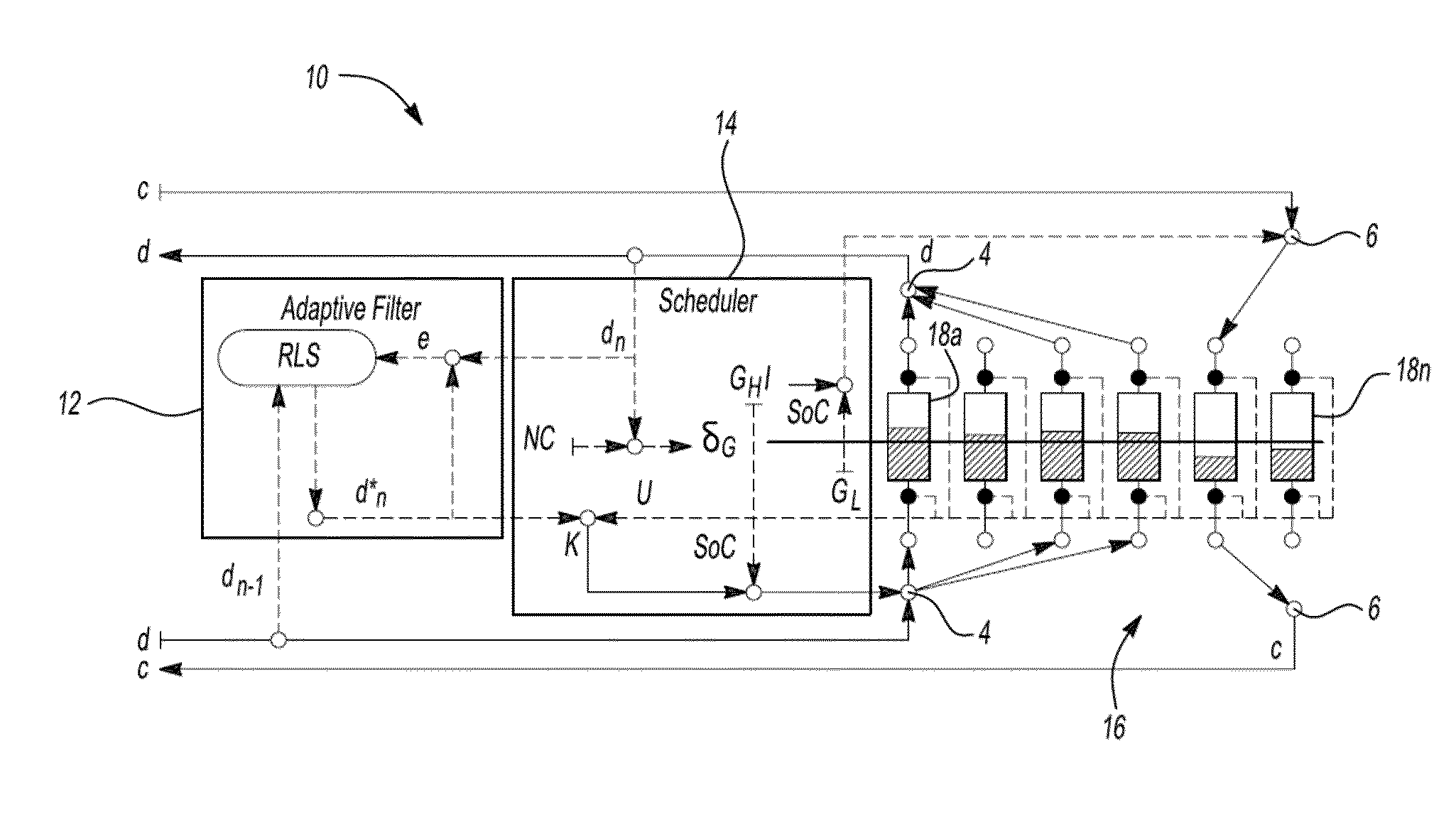
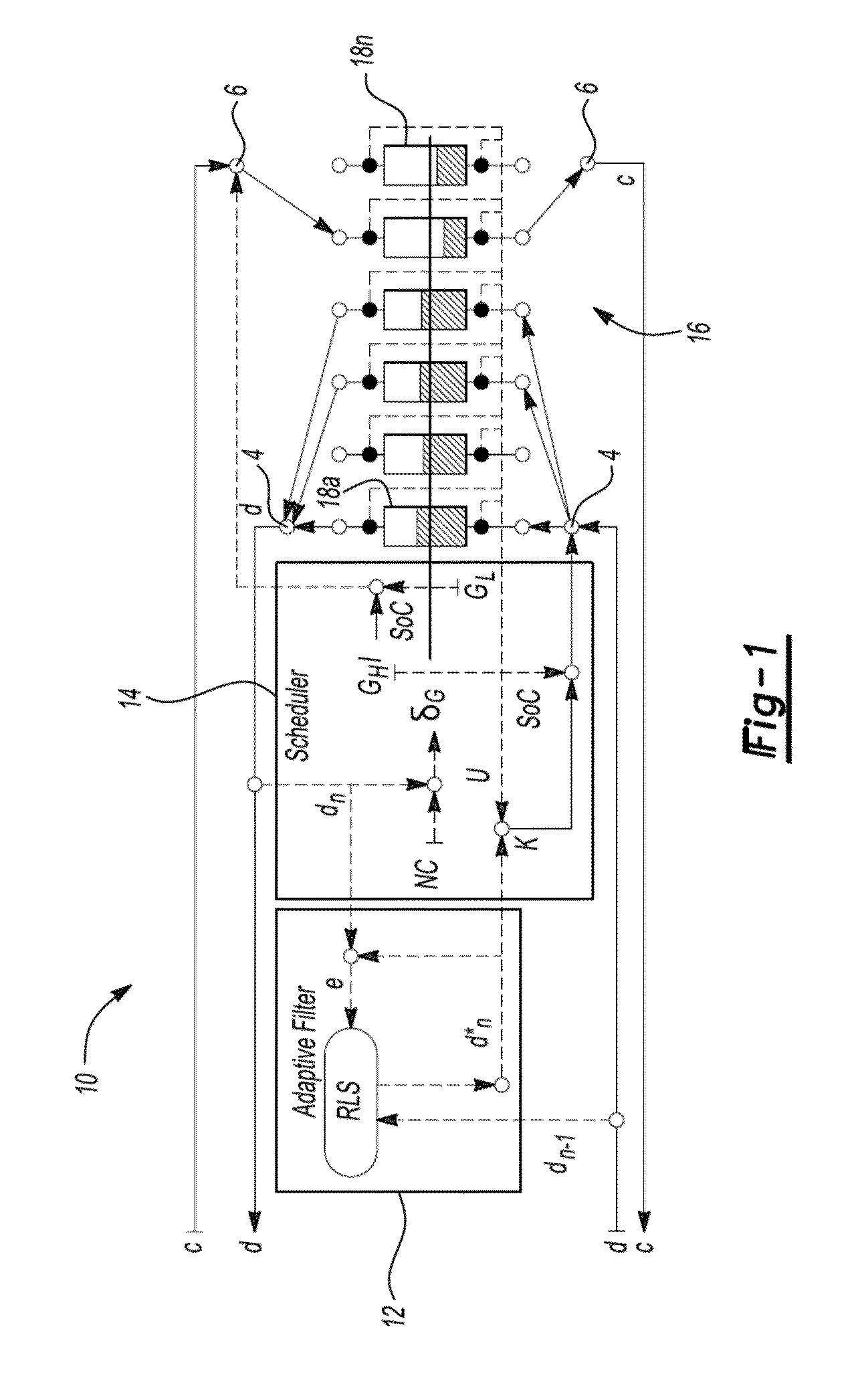
[0027]FIG. 1 depicts an exemplary battery management system 10. The battery management system 10 is comprised an adaptive filter module 12, a scheduler module 14 and a plurality of battery cells 18a-18n arranged in reconfigurable circuit paths. For purposes of this disclosure, a battery cell can refer to a single battery cell, a series chain of battery cells, a battery module, or a battery pack. The plurality of battery cells 18 are selectively interconnected to charger terminals 4, discharge terminals 6 and / or to each other by a plurality of switches (not shown). An exemplary arrangement for a reconfigurable battery cell circuit is described in U.S. patent application Ser. No. 12 / 757,293 filed on Apr. 9, 2010 and incorporated herein by reference. Other types of reconfigurable circuit arrangements are also within the scope of this disclosure.

[0028]Briefly, the input to the adaptive filter 12 is a history of the loads measured at certain intervals. An estimate of the upcoming load de...


PUM


Abstract

Effective scheduling of battery charge and discharge activities, by making the most of battery characteristics, can extend the battery pack's operation-time and lifetime. A system and method for scheduling battery activities is disclosed. This framework dynamically adapts battery activities to load demands and to the condition of individual battery cells, thereby extending the battery pack's operation-time and making them robust to anomalous voltage imbalances. The scheduling framework includes two components. An adaptive filter estimates the upcoming load demand. Based on the estimated load demand, a scheduler can determine the number of parallel-connected battery cells to be discharged. The scheduler also effectively partitions the battery cells in a pack, allowing the battery cells to be simultaneously charged and discharged in coordination with a reconfigurable battery circuit.

Description

[0001]This application is claims benefit of U.S. Provisional Application No. 61 / 229,291 filed on Jul. 29, 2009. The entire disclosure of the above application is incorporated herein by reference.FIELD[0002]The present disclosure relates to a system for scheduling battery charge and discharge that employs scheduling policies that allow battery cell activities to adapt to load demands and the conditions of individual cells.BACKGROUND[0003]Customers will eventually replace their gasoline-powered vehicles with rechargeable models. Accordingly to a McKinsey report by 2015, approximately 2 million electric vehicles (EVs) will be sold around the world. This replacement will lead to substantial decrease in carbon footprint. For instance, the replacement of 77% of all transport miles with EVs will reduce carbon intensity by 94% over the 1990 numbers. To meet this demand, automotive companies are taking tremendous efforts on enhancing battery technologies including battery cell manufacturing ...

Claims


Application Information

Patent Timeline
Patent Type & Authority Patents(United States)
IPC IPC(8): H02J7/00
CPCH02J7/0013H02J7/0063H02J2007/0067H02J7/0024H01M10/425H01M10/441H01M2010/4271H01M2220/20H02J7/0025Y02E60/10H02J7/0071
Inventor KIM, HAHNSANGSHIN, KANG G.
Owner RGT UNIV OF MICHIGAN
Why Eureka
Try Eureka