Microscope apparatus and microscopy method

a microscopy and microscope technology, applied in the field of microscope equipment, can solve the problems of laborious alignment of images obtained pre- or intra-operatively on the present microscope image, and the laborious alignment of images obtained pre- or intra-operatively on the microscope image,

Active Publication Date: 2013-08-13
LEICA MICROSYSTEMS (SCHWEIZ) AG
View PDF16 Cites 0 Cited by
  • Summary
  • Abstract
  • Description
  • Claims
  • Application Information

AI Technical Summary

Benefits of technology

[0010]The invention confers particular advantages particularly with respect to surgical interventions. The superimposing can be done quickly and easily, thus making it possible to increase the number of images that can be obtained during an operation. The length of time for which the operation may possibly have to be interrupted can be reduced significantly. Depending on the MR apparatus used, simultaneous image capture can also be carried out during the operation.
[0013]If the detectors are configured as articulated or joint sensors to determine the position of joints, the relative position of the two apparatus to each other can be determined very easily, as the dimensions of the arms of the stand or of the stand itself are known or, at the very least, can easily be determined
[0016]A single-sided MR apparatus may be used to particular advantage, as it can easily be connected to a stand for an operating microscope. Single-sided MR spectroscopy is described for example in EP 1 944 617 A1 and in the specifications cited in the associated Search Report, to which reference is hereby made for further details. Because of the advantageous construction of a single-sided MR apparatus in this case there are no special conditions regarding prevailing magnetic fields, with the result that conventional stands and operating microscopes can also be used. Compared with specially made constructions they are usually more tried and tested, more sophisticated and cheaper too. Overall, the microscope and MR apparatus form a unit, namely the microscope apparatus, which has significant advantages in the operating theatre. Instead of the patient being brought to the MR apparatus, the MR apparatus is brought to the patient. The costs and space requirements of previous diagnosis machines can be reduced. Patient safety is increased.
[0018]Advantageous applications for the invention can be found for example in ophthalmology for checking the positioning of an implanted lens (IOL), for examining the retina and / or the vitreous body. Another preferred field of use is the demarcation of tumours and distinguishing between tissues in brain and skin surgery. For example, one-, two- or three-dimensional profiles can be produced and spectral examinations can be carried out, avoiding the need for biopsies and examination of the biopsied tissue under an optical microscope.

Problems solved by technology

MR-assisted operations of this kind are, however, very laborious as the patient often has to be transported back and forth during the operation while at the same time the alignment of the patient in the different apparatus has to be altered constantly.
The alignment of images obtained pre- or intra-operatively on the present microscope image, however, is very laborious.

Method used


Image

  • Microscope apparatus and microscopy method
  • Microscope apparatus and microscopy method

Examples


Embodiment Construction

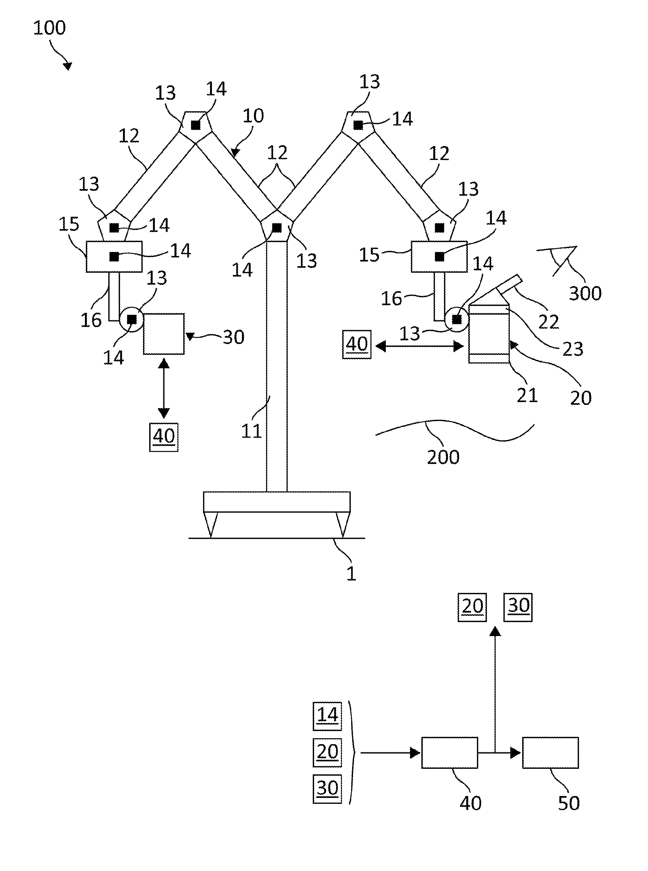
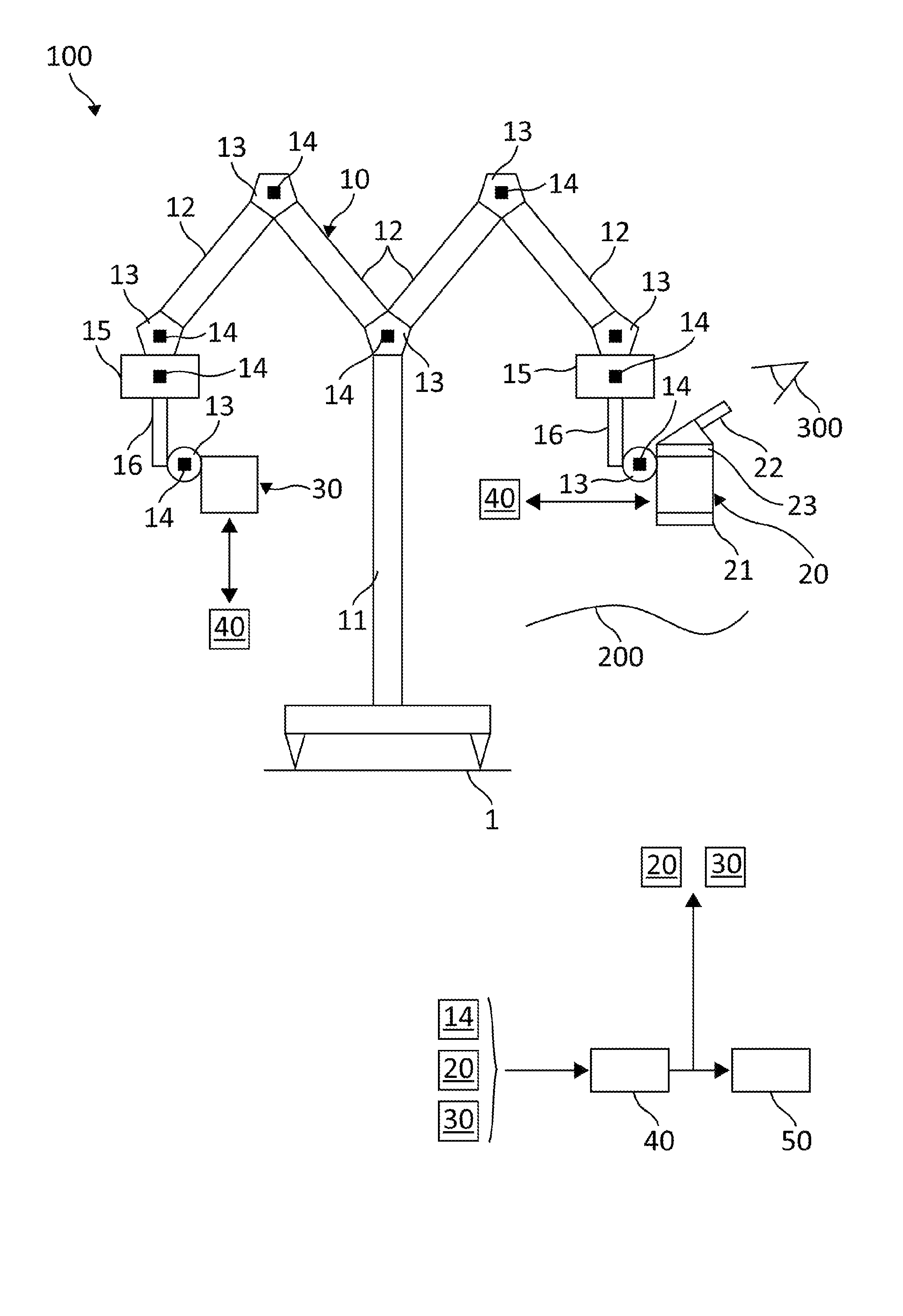
[0023]FIG. 1 shows the schematic side elevation of a microscope apparatus 100 with an operating microscope 20 and an MR apparatus 30, which are supported on a stand 10. The operating microscope 20 and expediently also the MR apparatus 30 are mounted on the stand so as to be movable in all three directions in space (by translatory and rotary movement). The MR apparatus 30 is configured here as a single-sided MR apparatus and can be used for imaging, so as to produce, for example, magnetic resonance tomography sections (MRT). The data captured using the MR apparatus are transmitted to a computer unit 40 to generate MRT images.

[0024]In the embodiment in FIG. 1 there is a floor stand 10 that stands on a floor 1. As an illustration, the operating microscope 20 and the MR apparatus 30 are shown on either side of a stand column 11. However, it will be understood that both apparatus are freely movable relative to the column and are usually arranged close together during an operation so that...


PUM


Abstract

The present invention relates to a microscope apparatus (100) comprisingan operating microscope (20),a magnetic resonance or MR apparatus (30),a stand (10) that carries the operating microscope (20) and the MR apparatus (30),at least one detector (14) for determining the spatial position of the MR apparatus (30) relative to the operating microscope (20),a reflecting device (23) for reflecting an image obtained using the MR apparatus (30) into at least one observation beam path of the operating microscope (20),a computer unit (40) which is connected to the at least one detector (14) and is arranged so as to determine the spatial position of the MR apparatus (20) relative to the operating microscope (30),the computer unit (40) being connected to the reflecting device (23) and to the MR apparatus (30) and being arranged so as to provide the image that is to be reflected in for the reflecting device (23) on the basis of the spatial position determined for the MR apparatus (30) relative to the operating microscope (20).

Description

CROSS-REFERENCE TO RELATED APPLICATIONS[0001]This Application claims priority to German Patent Application No. DE 10 2010 003 836.9 filed on Apr. 9, 2010, that is incorporated herein by reference in its entirety.FIELD OF THE INVENTION[0002]The present invention relates to a microscope apparatus comprising at least one operating microscope and a magnetic resonance or MR apparatus and a method of microscopy using a microscope apparatus of this kind.BACKGROUND OF THE INVENTION[0003]Magnetic resonance methods are referred to by various abbreviations, for example MRT, MRI, NMR, etc. It is known to use MR methods for imaging in microscope-assisted surgery. For example, they can make it possible to distinguish more easily between healthy and diseased tissue, so that a surgeon can tell, for example, whether he has removed all the tumour tissue. Methods of this kind are therefore particularly suitable in fields such as brain surgery, for example, in which it is important to remove neither to...

Claims


Application Information

Patent Timeline
Patent Type & Authority Patents(United States)
IPC IPC(8): G01V3/00
CPCA61B19/5223G02B21/0012G02B21/24G02B21/364A61B5/055A61B19/5244A61B2019/5236A61B2019/5289A61B34/20A61B90/20A61B2090/364A61B2090/374
Inventor SANDER, ULRICH
Owner LEICA MICROSYSTEMS (SCHWEIZ) AG
Why Eureka
Try Eureka