Spark ignition type internal combustion engine

a technology of internal combustion engine and spark ignition, which is applied in the direction of machines/engines, electrical control, output power, etc., can solve the problems of extremely large blowback of intake gas and extremely large blowback strength of intake gas

Active Publication Date: 2013-08-20
TOYOTA JIDOSHA KK
View PDF16 Cites 1 Cited by
  • Summary
  • Abstract
  • Description
  • Claims
  • Application Information

AI Technical Summary

Benefits of technology

[0012]In a second aspect of the present invention, at the time of engine cold operation, the lower a wall surface temperature of an intake system, the greater the extent by which the closing timing of the intake valve is advanced compared with the time of engine warm operation.

Problems solved by technology

In such a case, the amount of blowback of intake gas becomes extremely large or the strength of blowback of the intake gas becomes extremely great.
That is, at the time of engine cold start, the fuel which is injected from a fuel injector is difficult to atomize (or vaporize, below, “atomization” including “vaporization”) and parts where the fuel concentration is high and parts where the fuel concentration is low end up being formed in the air-fuel mixture in some cases.
However, if the blowback of the air-fuel mixture into the engine intake passage is slight and weak, the blown back air-fuel mixture will not be taken into other cylinders, but will again be taken into the cylinder in question at the next cycle.

Method used


Image

  • Spark ignition type internal combustion engine
  • Spark ignition type internal combustion engine
  • Spark ignition type internal combustion engine

Examples


first embodiment

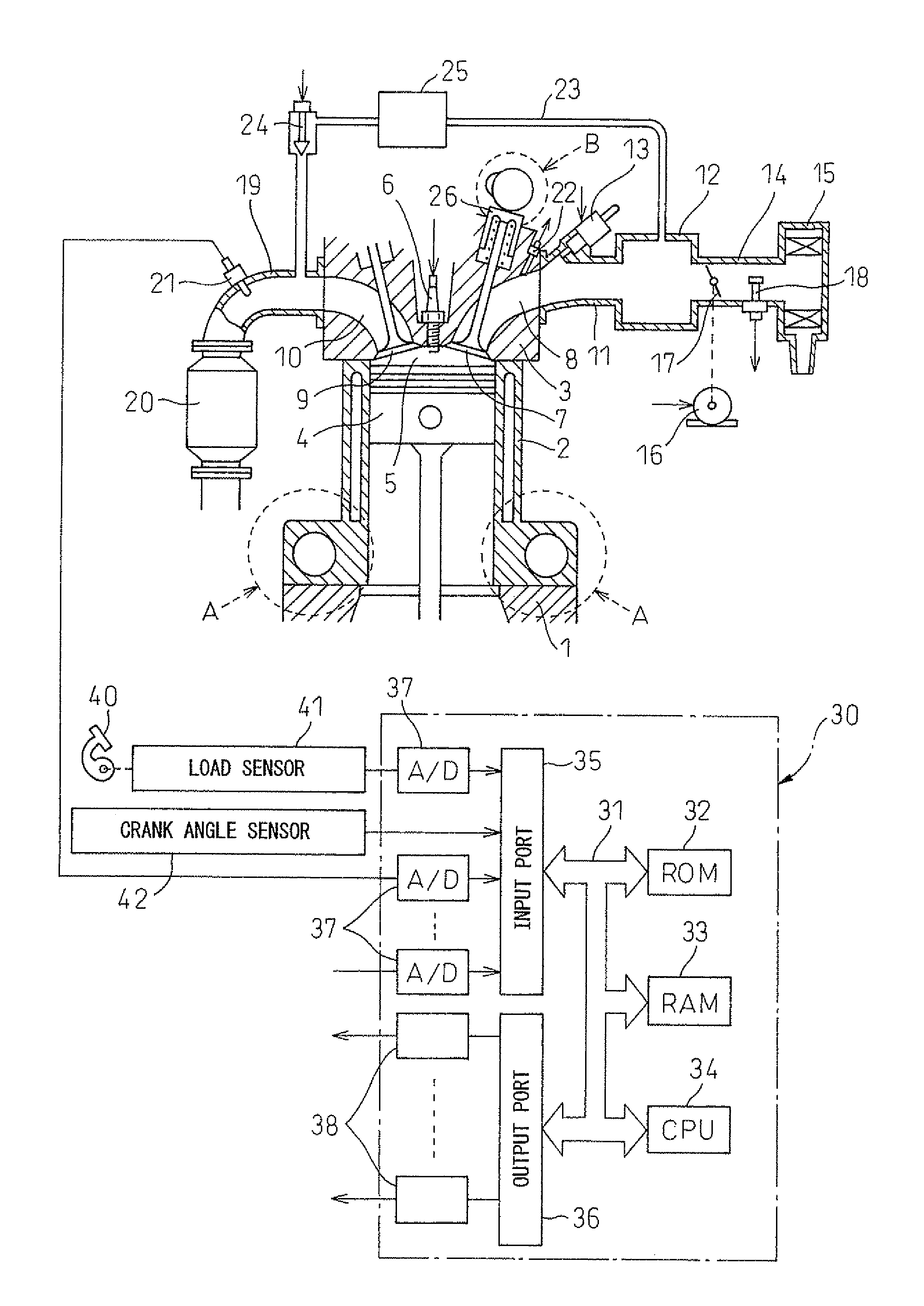
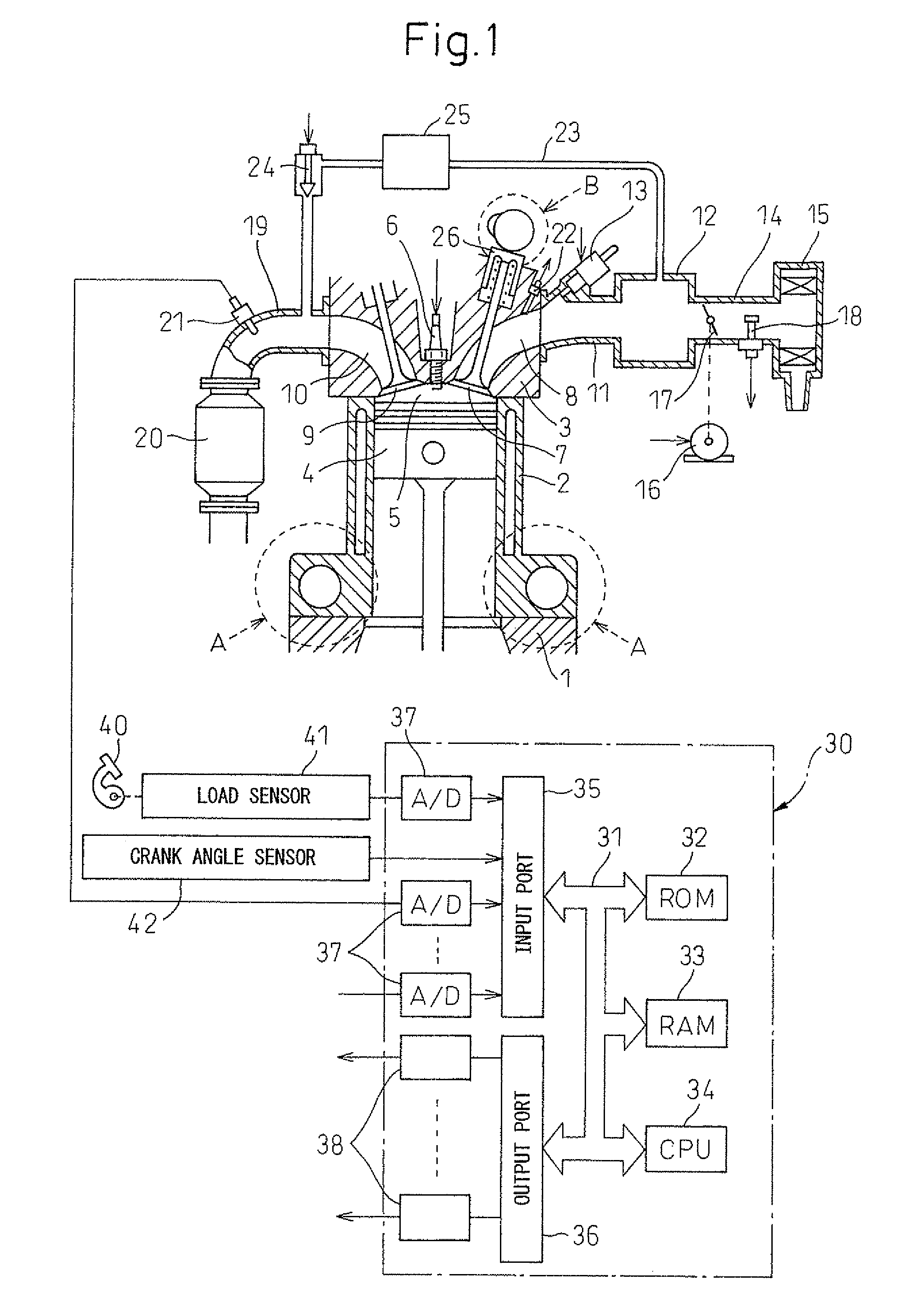
[0123]FIG. 14 is a flowchart showing of a control routine of the operational control of the present invention. As shown in FIG. 14, first, at step S11, the outputs of the load sensor 41 and the crank angle sensor 42 are used as the basis to detect the engine load L and engine speed Ne. Next, at step S12, the output of the wall surface temperature sensor 22 which detects the intake system wall surface temperature is used as to basis to detect the intake system wall surface temperature Ts. At step S13, it is judged if the intake system wall surface temperature Ts which is detected at step S12 is lower than a warmup judgment temperature Ts1. The warmup judgment temperature Ts1 is the minimum temperature of the intake system wall surface when the internal combustion engine finishes warming up. At the time of engine cold start, at step S13, it is judged that the intake system wall surface temperature Ts is lower than the warmup judgment temperature Ts1, then the routine proceeds to step ...

second embodiment

[0147]FIG. 18 and FIG. 19 are flowcharts of a control routine of the operational control of the present invention. Steps S31 to S33 and S41 to S43 of FIG. 18 and FIG. 19 are similar to steps S11 to S13 and S18 to S20 of FIG. 14, so explanations are omitted.

[0148]At step S34 of FIG. 18, the engine load L, engine speed Ne, etc. which were detected at step S31 are used as the basis to calculate the target closing timing tivc of the intake valve 7 by using a map etc. Next, at step S35, the intake system wall surface temperature Ts which was detected at step S32 was used as the basis to calculate the reference retarded guard timing givc of the closing of the intake valve using the map etc. shown by the solid line in FIG. 15. Next, at step S36, the engine speed Ne which was detected at step S31 is used as the basis to calculate the engine speed correction coefficient kne using a map such as shown in FIG. 16A, the engine load L which was detected at step S31 was used as the basis to calcul...


PUM


Abstract

A spark ignition type internal combustion engine of the present invention is provided with a variable closing timing mechanism which can change a closing timing of an intake valve after suction bottom dead center wherein the amount of intake air fed into a combustion chamber is controlled mainly by changing the closing timing of the intake valve. At the time of engine cold start, the closing timing of the intake valve is advanced compared with the time of engine warm operation. At the time of engine cold start, the air-fuel mixture which is taken into a combustion chamber is blown back into the engine intake passage whereby the air-fuel ratio varies among cylinders, but according to the spark ignition type internal combustion engine of the present invention, it is possible to suppress such variation in the air-fuel ratio among cylinders.

Description

TECHNICAL FIELD[0001]The present invention relates to a spark ignition type internal combustion engine.BACKGROUND ART[0002]The present applicant proposed in Japanese Patent Publication (A) No. 2007-303423 a spark ignition type internal combustion engine which is provided with a variable compression ratio mechanism which can change a mechanical compression ratio and with a variable closing timing mechanism which can change a closing timing of the intake valve and which raises the mechanical compression ratio to 20 or more at the time of engine low load operation compared with at the time of engine high load operation.[0003]In this spark ignition type internal combustion engine, at the time of engine low load operation, by making the mechanical compression ratio (expansion ratio) 20 or more and by making the closing timing of the intake valve a timing away from suction bottom dead center, the actual compression ratio is maintained comparatively low compared with the mechanical actual ...

Claims


Application Information

Patent Timeline
Patent Type & Authority Patents(United States)
IPC IPC(8): F02D41/06
CPCF02D13/0226F02D41/047F02D41/064F02D9/02F02D13/0234F02D15/04F02D2041/001F02D2041/002Y02T10/18F02D41/0002F02D2200/021Y02T10/12Y02T10/40
Inventor AKIHISA, DAISUKEYOSHIOKA, MAMORU
Owner TOYOTA JIDOSHA KK
Why Eureka
Try Eureka