Drill assembly and method to reduce drill bit plunge

a drill bit and assembly technology, applied in the field of drill bit assembly and method to reduce drill bit plunge, can solve the problems of time-consuming process, large skill and experience, and costly scan of the area to be drilled, so as to reduce the plunge of the leading edge and reduce the plunge of the drill bit

Active Publication Date: 2013-08-20
QUANSER CONSULTING
View PDF49 Cites 50 Cited by
  • Summary
  • Abstract
  • Description
  • Claims
  • Application Information

AI Technical Summary

Benefits of technology

[0006]It is therefore an object of the invention to provide a drill assembly and method to reduce plunge of the leading edge of a rotating drill bit when the drill bit penetrates a workpiece.
[0007]One aspect of the invention provides for a drill assembly with a drill body, a drill bit rotatably coupled to the drill body, a motor for advancing and retracting the drill bit relative to the drill body, at least one sensor for monitoring the advancement and retraction of the drill bit, and a control unit connected to the motor and at least one sensor, the control unit, on detecting a breakthrough of the drill bit, controlling the motor to reduce plunge of the drill bit.
[0008]It is another aspect of the invention to provide a method for reducing plunge of a drill bit through a workpiece by initiating advancement of the drill bit towards the workpiece and detecting the drill bit breaking through the workpiece. It is a further aspect of the invention to maintain a desired stiffness in the forward motion of the drill bit.

Problems solved by technology

This process may be time consuming and require considerable skill and experience from the surgeon.
Other methods require a costly scan of the area to be drilled to accurately determine the thickness of the bone.
Failure to accurately detect penetration through the bone or applying too much force to the drill can result in the drill bit plunging through the bone and damaging sensitive tissue.
This distance may extend well through the workpiece resulting in a wasted movement of the drill bit.

Method used


Image

  • Drill assembly and method to reduce drill bit plunge
  • Drill assembly and method to reduce drill bit plunge
  • Drill assembly and method to reduce drill bit plunge

Examples


Embodiment Construction

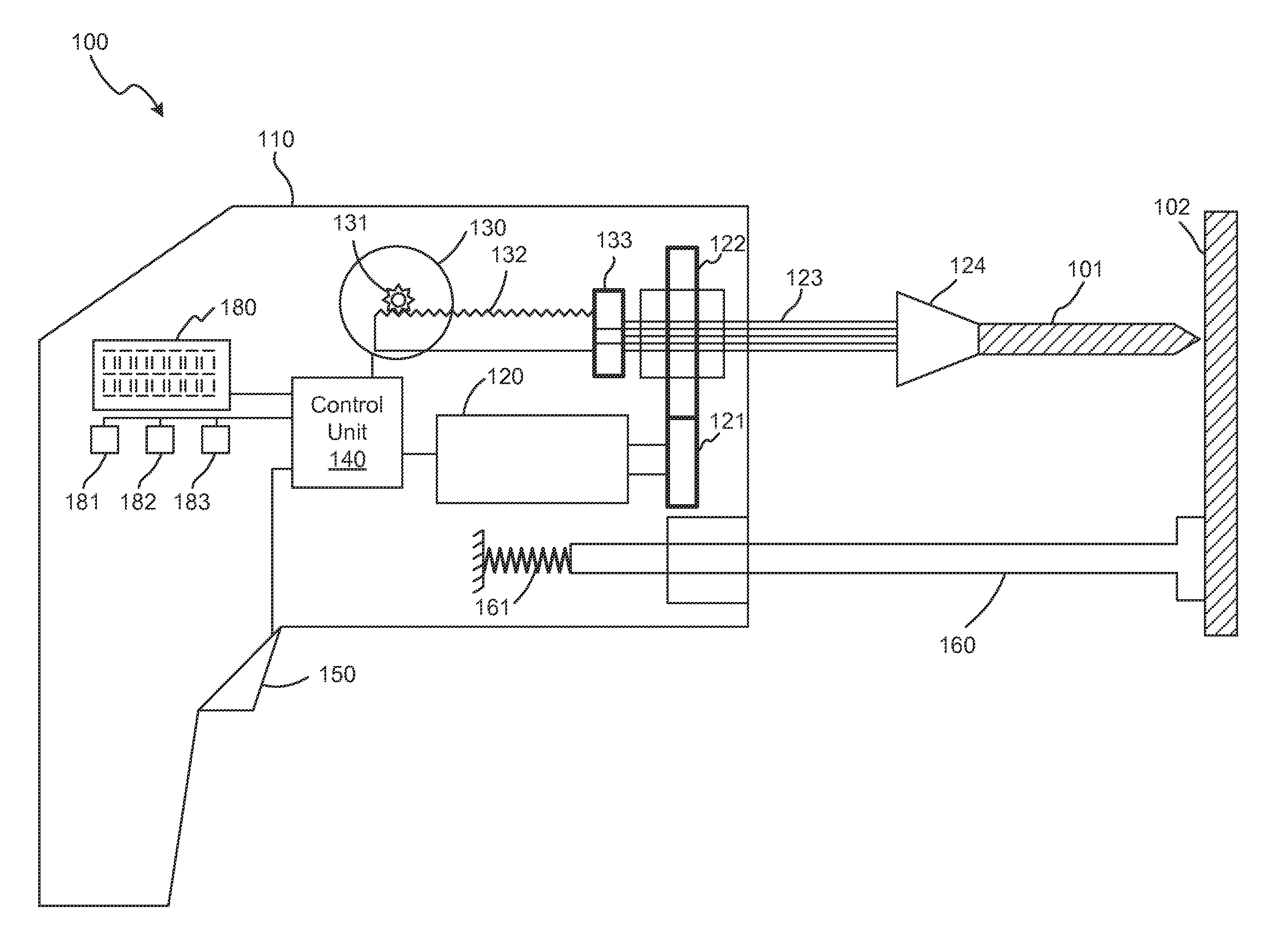
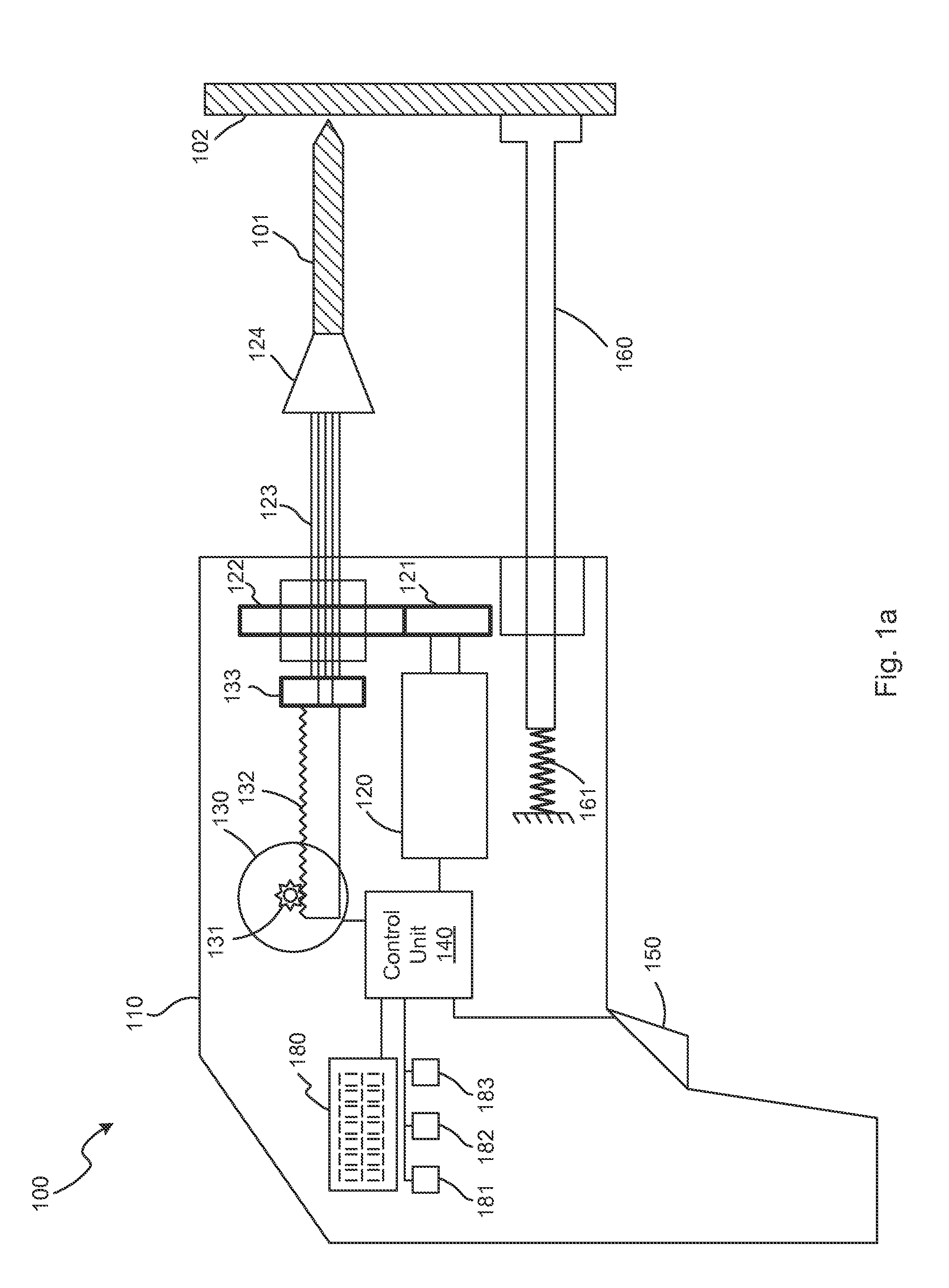
[0016]Referring now to FIG. 1a, shown is a side functional view of an embodiment of a drill assembly 100 to reduce plunge upon breakthrough. The drill body 110 provides a casing to enclose the elements of the drill assembly 100. The drill body 110 contains two motors for controlling the motion of the drill bit 101. The workpiece 102, depending on the application, may be any object that requires machining, and may also be human tissue such as bone.

[0017]The first motor 130, is responsible for advancing and retracting the drill bit relative to the drill body 110. The motor 130 is attached to drive pinion 131, which in turn is mated to the rack 132 to translate the rotational movement of the motor 130 to a linear motion. Other known mechanisms may be used to generate the advancing and retracting of the drill bit, for example, using a capstan, a lead screw, or a friction drive.

[0018]The second motor 120, is responsible for providing the rotational movement for the drill bit 101. The sec...


PUM

PropertyMeasurementUnit
speedaaaaaaaaaa
stiffnessaaaaaaaaaa
torqueaaaaaaaaaa

Abstract

A drill assembly and method for reducing plunge of a drill bit upon breaking through a workpiece. The drill assembly contains a motor to advance and retract the drill bit, the motor is controlled by a control unit in a feedback loop to achieve a desired stiffness. The control unit determines when the drill bit breaks through the workpiece and stops or retracts the movement of the drill bit.

Description

[0001]This application claims the benefit of Provisional Application No. 61 / 040,374, filed Mar. 28, 2008, which is hereby incorporated herein by reference.FIELD[0002]The present invention relates generally to a drill assembly and method for reducing plunge of the leading edge of a rotating drill bit when the drill bit penetrates a workpiece.INTRODUCTION[0003]There are many applications where having a drill bit automatically retract after penetrating through a workpiece may be beneficial. For example, in the medical field, a surgical drill that automatically retracts upon penetrating through bone matter may provide greater precision and safety. Manufacturing applications may also benefit from a drill machine with an automatically retracting drill bit through increased speed and efficiency. A power drill incorporating the present invention may also be attractive to the consumer market for providing greater efficiency and safety.[0004]Presently, surgical drills require the surgeon to a...

Claims


Application Information

Patent Timeline
Patent Type & Authority Patents(United States)
IPC IPC(8): B23B35/00B23B45/14
CPCA61B17/1626A61B17/1695B23B49/00A61B2019/462B23B2260/0482Y10T408/5653Y10T408/172Y10T408/03Y10T408/173Y10T408/15B23B2260/128A61B2090/062A61B34/30
Inventor APKARIAN, J. G. AGOPKARAM, PAULGARDNER, DON
Owner QUANSER CONSULTING
Why Eureka
Try Eureka