Ion pump system and electromagnetic field generator

a technology of electromagnetic field and pump system, which is applied in the direction of pump components, dynamo-electric machines, particle separator tubes, etc., can solve the problems of unidirectional magnetic field, inability to make effective use of space in ion pumps, and vulnerable surface of semiconductors to gas molecules pollution, etc., to achieve high air-exhausting capacity, vacuum-maintaining capacity, and high connectivity with other devices

Active Publication Date: 2013-08-20
NAT INST OF INFORMATION & COMM TECH
View PDF45 Cites 3 Cited by
  • Summary
  • Abstract
  • Description
  • Claims
  • Application Information

AI Technical Summary

Benefits of technology

[0114]According to the present invention, a small ion pump system can be provided.
[0115]According to the present invention, an ion pump system having a high air-exhausting capacity and vacuum-maintaining capacity can be provided.
[0116]According to the present invention, an ion pump system capable of adjusting drive modes suitable for the uses thereof can be provided.
[0117]According to the present invention, an ion pump system having high connectivity with other devices can be provided.
[0118]According to the present invention, an ion pump system capable of making room internally insusceptible to electromagnetic fields at low cost can be provided. Furthermore, according to the present invention, an electromagnetic field generator wherein space insusceptible to electromagnetic fields is a fluid passage can be provided.

Problems solved by technology

Semiconductor surfaces are vulnerable to pollution from gas molecules.
This makes a magnetic field unidirectional, making it impossible to make effective use of space in an ion pump.
However, such ion pumps need to use many insulators such as ceramics in order to obtain insulation between electrodes.
For this reason, there is a problem that gases are emitted from ceramics etc., lowering a degree of vacuum.
There is also a problem that such ion pumps do not have enough intensity.
Furthermore, such ion pumps are large and heavy, and their power consumption is also large.
Therefore, there is a problem that once the conventional ion pumps are located they cannot be moved easily.
Moreover, there is a problem of low connectivity with other devices.
Furthermore, there is a problem that the ion pumps as described above, in order to make space therein insusceptible to electromagnetic field, require special magnetic field shielding structure for installation, resulting in high cost.

Method used


Image

  • Ion pump system and electromagnetic field generator
  • Ion pump system and electromagnetic field generator
  • Ion pump system and electromagnetic field generator

Examples


Embodiment Construction

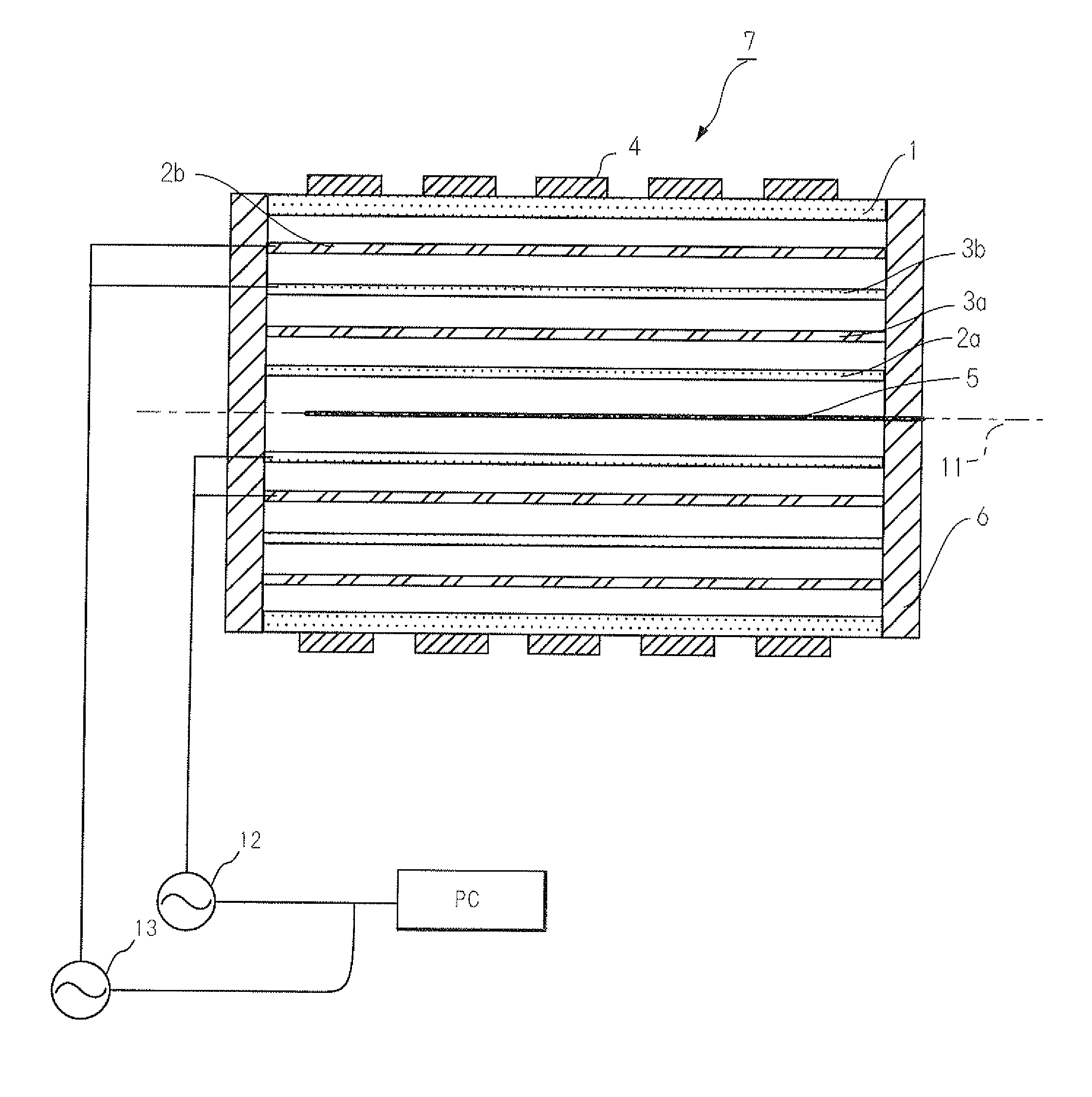
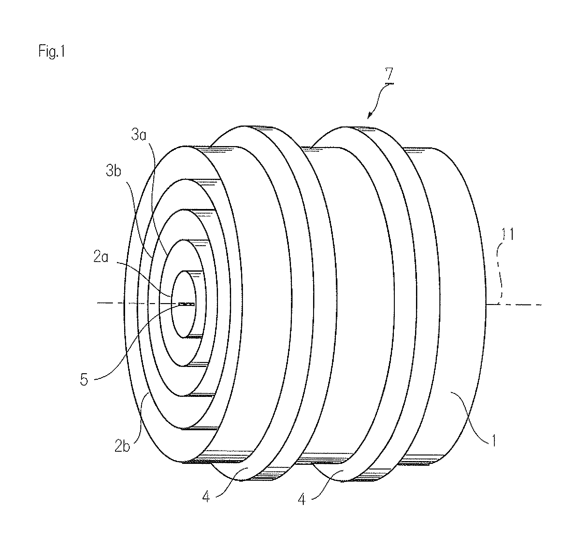
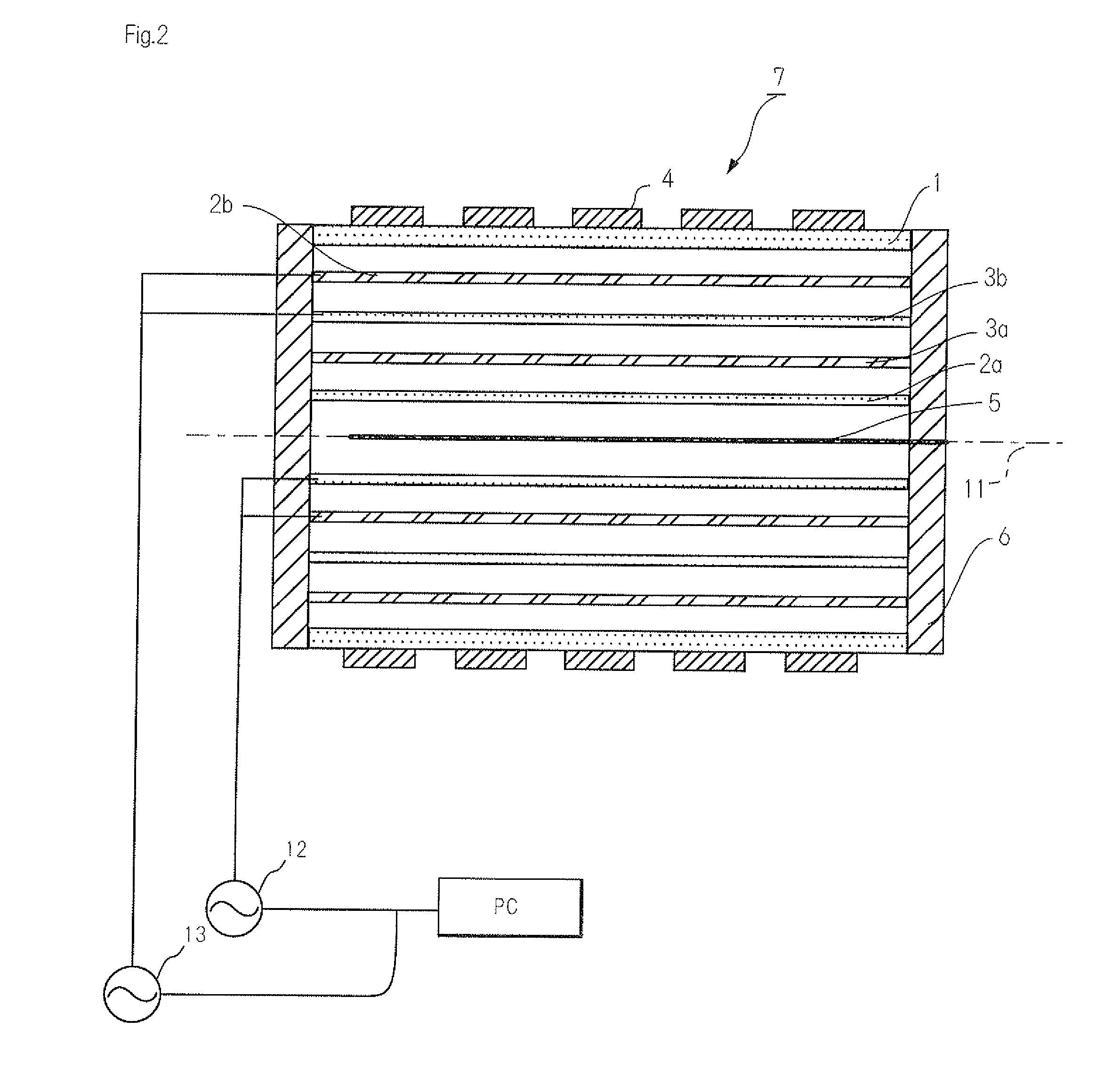
[0162]Hereinafter, embodiments for carrying out the present invention will be described with reference to the accompanying figures. FIG. 1 is a conceptual diagram for explaining an ion pump system of the present invention. Also, FIG. 2 is a conceptual diagram showing a cross-section view of an ion pump system. FIG. 1 shows an ion pump system cut in the middle in order to show well electrodes. The first aspect of the present invention relates to an ion pump system having two pump parts. As shown in FIGS. 1 and 2, an ion pump system (7) according to the first aspect of the present invention comprises a casing (1), a first electrode group (2a, 2b), a second electrode group (3a, 3b), outer magnets (4) and an inner magnet (5). A casing (1) comprises a connecting part (6).

[0163]In this way, an ion pump system (7) of the present invention has a plurality of electrodes inside a casing (1). This can increase the getter electrode area and plasma generation. As a result, an ion pump system (7)...


PUM


Abstract

It is an object of the present invention to provide an ion pump system etc. having a high air-exhausting capacity and vacuum-maintaining capacity and capable of adjusting drive modes suitable for the uses thereof. The subject problem is solved by an ion pump system (7) comprising a casing (1), a first electrode group (2a,2b) provided in the casing (1), a second electrode group (3a,3b) provided on the outer periphery of the first electrode group (2a,2b), and outer magnets (4) for providing a magnetic field in the casing, wherein the first electrode group (2a,2b) and the second electrode group (3a,3b) are constituted as a plurality of layers alternately disposed around the center axis (11) of the casing (1).

Description

FIELD OF INVENTION[0001]The present invention relates to an ion pump system etc. having a plurality of electrode layers. For example, the present invention relates to a lightweight and low power consumption multimode ion pump system etc. having operational modes according to loads.DESCRIPTION OF THE RELATED ART[0002]With the developments in nanotechnology and ultraprecise measuring technique, ultrahigh vacuum technology has been emphasized. Semiconductor surfaces are vulnerable to pollution from gas molecules. On the other hand, clean semiconductor surfaces can be maintained by maintaining semiconductors in ultrahigh vacuum under around 10−7 Pa. And, in order to maintain ultrahigh vacuum, pumps such as an ion pump are used.[0003]As for conventional ion pumps, as shown in FIGS. 4(A) and 4(B) in JPA H9-27294, tabular permanent magnets are arranged parallel to each other across a cuboid container. This makes a magnetic field unidirectional, making it impossible to make effective use of...

Claims


Application Information

Patent Timeline
Patent Type & Authority Patents(United States)
IPC IPC(8): F04B37/02F04F99/00
CPCH01J41/20F04B37/02
Inventor TANAKA, SHUKICHI
Owner NAT INST OF INFORMATION & COMM TECH
Why Eureka
Try Eureka