Door with glass pane for dryer

a dryer and glass pane technology, applied in the field of doors or covers, can solve the problems of not making known the method of reversing the door or lid of the dryer, and the inability to reverse the door or cover, so as to increase the selling price, easy to assemble, and the effect of less high-costing pieces

Active Publication Date: 2013-09-03
MABE SA DE CV
View PDF29 Cites 17 Cited by
  • Summary
  • Abstract
  • Description
  • Claims
  • Application Information

AI Technical Summary

Benefits of technology

[0013]The present invention focuses on resolving all of the previously mentioned deficiencies in the same door or cover for the dryer. That is to say, the present invention's door or cover is a door or cover for a dryer with a low production cost, which has a space to visualize the dryer's inner content, which has a high safety factor for the operator, where the temperature levels of the parts which could potentially be in contact with the operator remain within the specified levels, and which has long durability and which is also reversible.
[0014]The door or cover assembly for dryers in the present invention comprises an inner door or cover, an outer frame and a tempered glass between the inner door or cover and the outer frame. The inner door or cover fastened unto the tempered glass by means of at least four retainers and at least four screws which fasten unto the retainers of the door or cover. The retainers exert a constant pressure on the tempered glass, pressure which is translated into force which said tempered glass exerts as a constant pressure unto a seal on the inner door or cover's inner face. The seal is coupled to the inner door or cover's inner face by a plurality of grooves distributed near the border or outer perimeter of the inner face, which anchor the seal to the inner door or cover's inner face. The compression forces between the inner door or cover and the tempered glass, and the back compression force between the cabinet, specifically the dryer's front panel, and the inner door or cover's seal, avoids air leaks from the dryer's interior and guarantees a uniform seal. Packaging is present between each one of the retainers and the tempered glass to avoid contact between the retainers and the tempered glass. Specifically, the packaging surrounds at least a part of the tempered glass border. Conversely, an outer frame is fastened to the inner door or cover by means of at least six screws distributed along the length of and close to the border of the outer frame and are received by holes on the inner door or cover. The handle is mechanically assembled to the outer frame.
[0018]Another aspect of the present invention is to provide a door or cover for dryers with a space to visualize the inner content of a dryer which is easy to assemble and which contain few high costing pieces.

Problems solved by technology

Additionally, one of the problems which can arise on the doors or lids in the previous art is that the doors or lids of household appliances, especially of dryers, can be non-reversible.
Thus, the previous art does not make known a door or cover for a household appliance, specifically for a dryer, which has a single glass pane and which is reversible.
In the same way, previous art does not make known a method to reverse the door or cover for a single glass pane for a dryer.

Method used


Image

  • Door with glass pane for dryer
  • Door with glass pane for dryer
  • Door with glass pane for dryer

Examples


first embodiment

[0066]The following description makes general reference to FIGS. 2 through 5A.

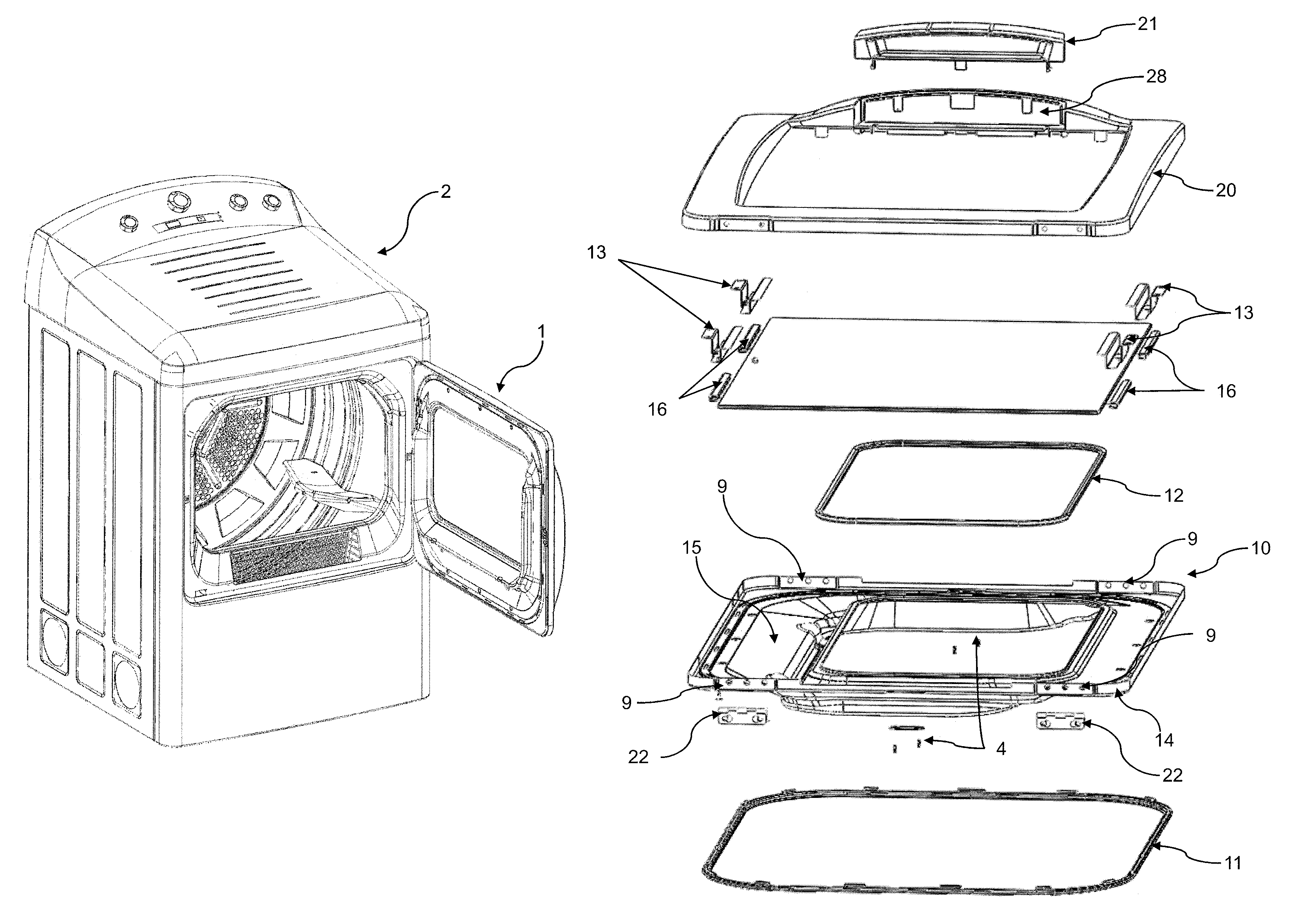
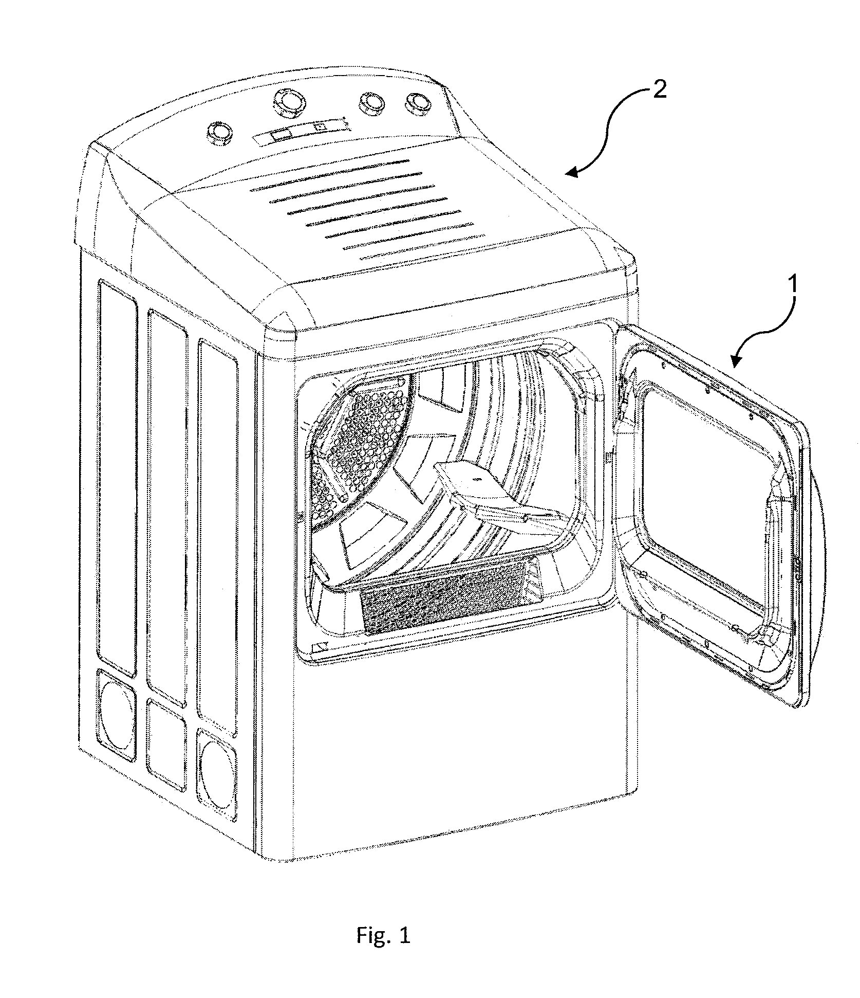
[0067]In the present invention, a door for household appliances is made known, preferably one for dryers 2. The dryers 2 can be front loading, such as the one shown in FIG. 1, or rather can be top loading or inclined as was known in previous art.

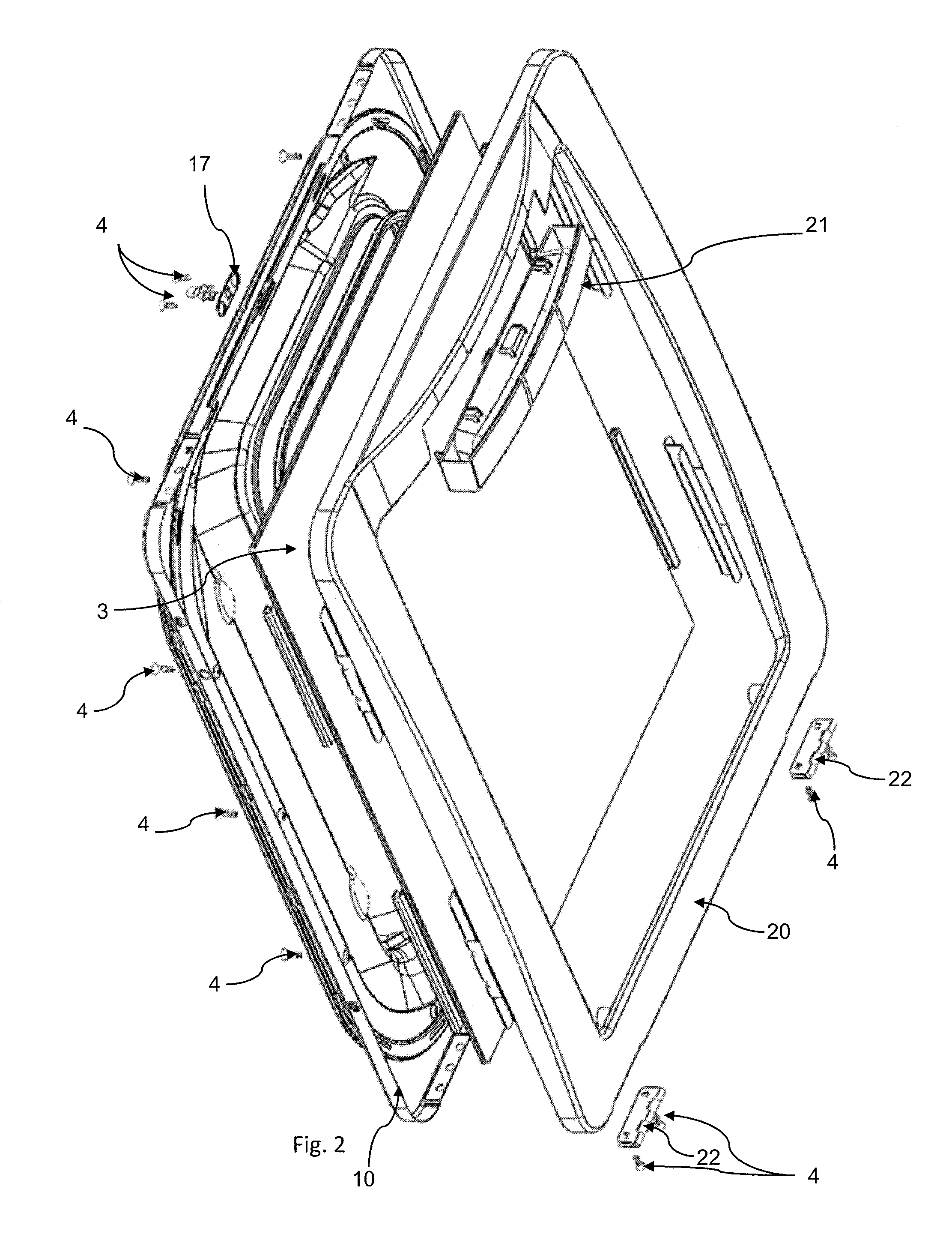
[0068]The main parts of the door 1 are an inner frame 10, an outer frame 20 and a tempered glass pane 3 between the inner frame 10 and the outer frame 20. FIGS. 2 and 3 are views in explosion which show the outer frame 20, the inner frame 10 and the tempered glass 3 and the union between all these parts. Such as its name denotes, the outer frame 20, when the dryer door 1 is closed is outwardly oriented in relation to the dryer 2, while the inner frame 10 is inwardly oriented in relation to the dryer 2 when the door is on a closed position.

[0069]FIGS. 2 and 3 show the majority of the components necessary for the first embodiment. Thus, the inner frame 10, the outer ...

second embodiment

[0072]In FIG. 5B a second embodiment can be seen. Specifically, in the second embodiment, several pieces can be dispensed with. Specifically, the retainers, the corresponding packaging for the retainers, the fastening means related to the retainers and the second seal, can be dispensed with. Specifically, over a gutter 30 of the inner frame, a constant silicon based strip 80 is provided. The strip has a width of approximately between 0.5 centimeters to 10 centimeters, and is deposited at a constant velocity approximately varying between 120 mm / second to 180 mm / second, preferably approximately between 135 mm / second and 160 mm / second and even more preferably approximately between 145 mm / second and 152 mm / second. The silicon's exit pressure varies approximately between 80 and 92 psi, more preferably between approximately 84 to 90 psi, and even more preferably approximately between 84 to 87 psi.

[0073]After the strip 80 deposit over the gutter 30, the tempered glass 3 is deposited over t...


PUM


Abstract

A door with a window for an appliance, such as a clothes dryer, and a method for assembling such a door in the appliance are provided. A tempered glass pane may be supported by one or more packaging structures disposed on borders of the glass pane. Each packaging structure may accommodate a retainer. The glass pane may be sandwiched between an inner frame and an outer frame coupled to one another to form a joined assembly effective to tightly seal the borders of the glass pane.

Description

RELATED APPLICATIONS[0001]This application claims priority from Mexican application Ser. No. MX / a / 2010 / 05581, filed May 19, 2010, which is incorporated herein by reference in its entirety.FIELD OF INVENTION[0002]The present application relates to a door or cover for a household appliance with a sole glass piece and more specifically to a reversible door or cover for a dryer which has a single glass pane, as well as the assembly pieces for said door or cover.BACKGROUND[0003]It is common for door or cover assemblies for household appliances, especially those in washers and dryers, and more specifically in the field of dryers, to have a window with at least two layers, where as an example, the two layers can be two glass panes, an inner glass pane which is in contact with the textiles and an outer glass pane which can have contact with the operator, or yet a glass pane as an inner window and a thermoplastic polymer laminate such as polycarbonate as an outer window. The advantage of hav...

Claims


Application Information

Patent Timeline
Patent Type & Authority Patents(United States)
IPC IPC(8): A47B77/06
CPCD06F39/14D06F58/04D06F58/20E05D15/00E05B65/00E05C3/16A47B96/00D06F37/42F24C15/04
Inventor NAJERA BERNAL, DANIELPEREZ MAZA, ROBERTOREYES MIRANDA, SERGIO
Owner MABE SA DE CV
Why Eureka
Try Eureka