Optically addressed light valve

a technology of light valves and light channels, applied in non-linear optics, instruments, optics, etc., can solve problems such as saturation or dazzle especially by lasers, damage to sensors, and degradation of image quality or user situational awareness, and achieve the effect of reducing the number of lasers

Inactive Publication Date: 2013-09-03
THE SEC OF STATE FOR DEFENCE IN HER BRITANNIC MAJESTYS GOVERNMENT OF THE UK OF GREAT BRITAIN & NORTHERN IRELAND
View PDF15 Cites 19 Cited by
  • Summary
  • Abstract
  • Description
  • Claims
  • Application Information

AI Technical Summary

Benefits of technology

[0017]If the input and output polarizers are crossed the device will not be transmissive to high intensity light, whilst low level light is transmitted unaffected by the device.
[0018]By positioning an OALV in accordance with the invention at or near a focal plane of an optical system or imaging device, high intensity incident light is focused to a point on the OALV. Therefore, the device will block only the focused point of dazzle allowing the user to view the remainder of the image clearly.

Problems solved by technology

Dazzle, by high intensity light sources, is a common problem in optical systems or imaging devices, causing damage to the sensor, degradation of image quality or loss of situational awareness for the user.
The problem occurs when high intensity light sources such as sunlight, welding arc, car head lamps or lasers are directed at the system or device.
Saturation or dazzle especially by laser is now a common problem, both in military and civilian environments, as lasers themselves have become smaller, cheaper and more readily available.

Method used


Image

  • Optically addressed light valve
  • Optically addressed light valve
  • Optically addressed light valve

Examples


Embodiment Construction

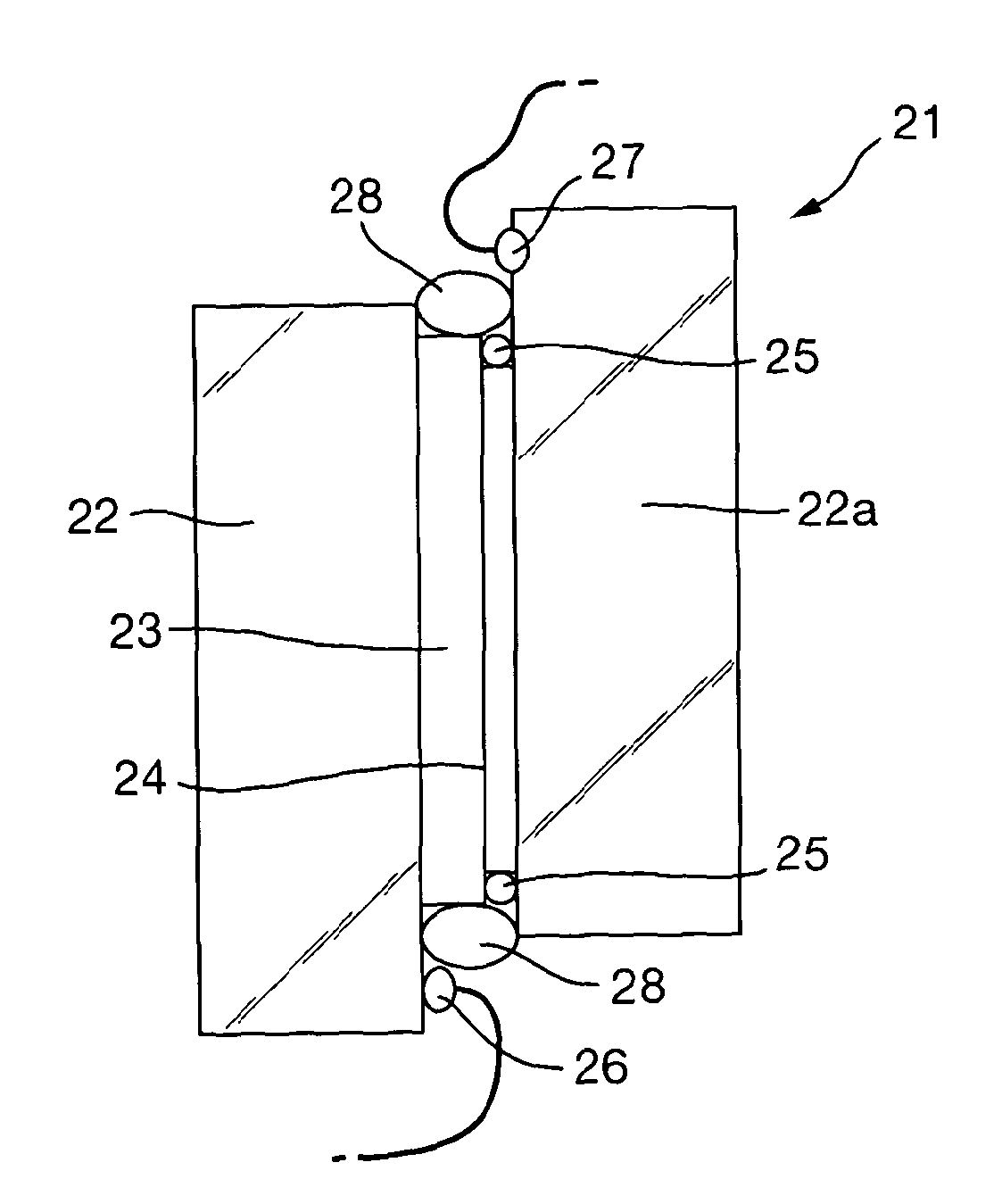
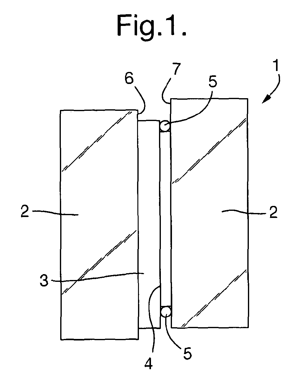
[0026]FIG. 1 illustrates a standard OALV design 1. Two glass plates are coated with transparent Indium Tin Oxide (ITO), to provide glass electrodes 2. A photoresistor 3 is coupled to a liquid crystal layer 4, with spacers 5 positioned to form a gap into which the liquid crystal is tilled by capillary action. The glass electrodes 2 are electrically connected to a voltage 6 and to earth 7. These electrical connections 6 and 7 allow a sinusoidal or square wave voltage to be applied across the glass electrodes 2. These glass electrodes 2 are spin coated with a polymer layer and rubbed unidirectionally such that the local liquid crystal layer 4 orientation is determined by the rubbing direction. By constructing the device such that the two rubbing directions are orthogonal, a 90 degree helical structure is set up within the liquid crystal layer 4. This is known as a twisted nematic. Twisted nematic layers are voltage-dependent polarisation modulators.

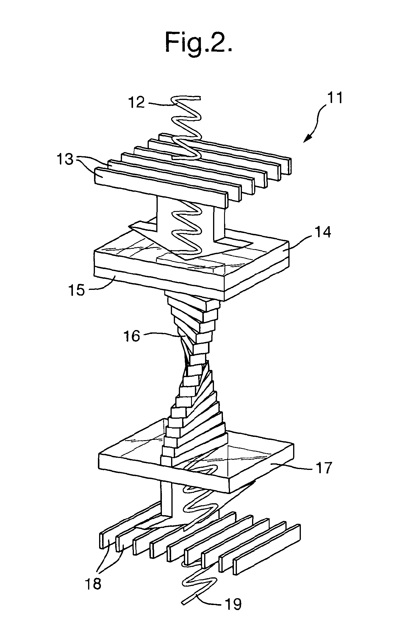
[0027]FIG. 2 illustrates the effect o...


PUM

PropertyMeasurementUnit
total twist angleaaaaaaaaaa
transparentaaaaaaaaaa
monochromatic wavelengthsaaaaaaaaaa

Abstract

An optically addressed light valve suitable for selectively limiting the transmission of radiation from high intensity light sources independent of wavelength using a TN liquid crystal cell and a photoconductive material (vanadium doped silicon carbide).

Description

CROSS REFERENCE TO RELATED APPLICATIONS[0001]This application is the U.S. national phase of International Application No. PCT / GB2010 / 001349 filed on Jul. 15, 2010, and published in English on Jan. 20, 2011, as International Publication No. WO 2011 / 007143 A1, which application claims priority to Great Britain Patent Application No. 0912241.7 filed on Jul. 15, 2009, and Great Britain Patent Application No. 0916089.6 filed on Sep. 15, 2009, the contents of all of which are incorporated herein by reference.TECHNICAL FIELD OF THE INVENTION[0002]This invention relates to an optically addressed light valve and more particularly to an optically addressed light valve suitable for selectively limiting the transmission of radiation from high intensity light sources independent of wavelength.BACKGROUND TO THE INVENTION[0003]Dazzle, by high intensity light sources, is a common problem in optical systems or imaging devices, causing damage to the sensor, degradation of image quality or loss of sit...

Claims


Application Information

Patent Timeline
Patent Type & Authority Patents(United States)
IPC IPC(8): G02F1/135
CPCG02F1/1354G02F1/1396G02F2001/1355G02F2203/04G02F1/1355G02F1/135
Inventor BURGESS, CHRISTOPHER DAVID
Owner THE SEC OF STATE FOR DEFENCE IN HER BRITANNIC MAJESTYS GOVERNMENT OF THE UK OF GREAT BRITAIN & NORTHERN IRELAND
Why Eureka
Try Eureka