
Rotary degasser and rotor therefor

a rotary degasser and rotor technology, which is applied in the direction of lighting and heating apparatus, charge manipulation, furniture, etc., can solve the problems of insufficient removal of impurities many known devices do not efficiently disperse gas into insufficient mixing of gas in the molten metal bath, etc., to achieve the effect of facilitating better mixing

Active Publication Date: 2013-09-17
MOLTEN METAL EQUIP INNOVIATIONS LLC
View PDF471 Cites 73 Cited by
  • Summary
  • Abstract
  • Description
  • Claims
  • Application Information

AI Technical Summary

Benefits of technology

The patent describes an impeller that is designed to mix molten metal with gas efficiently in a vessel. The impeller has a top portion that is shaped to prevent gas from escaping without mixing with the molten metal. The impeller rotates and displaces the molten metal / gas mixture radially as it rotates. This results in better mixing of the two materials without the need for excessive gas bubbling at the surface of the molten metal. The technical effect of this design is improved mixing of molten metal and gas, thereby increasing the efficiency of the process.

Problems solved by technology

Such techniques suffer from the drawback that there is often inadequate dispersion of the gas throughout the molten metal.
Many known devices do not efficiently disperse gas into the molten metal bath.
Therefore, the impurities in the molten metal are not adequately removed and / or an inordinate amount of gas is used to remove the impurities.
This inefficiency is a function of, among other things, (1) an inability to create small gas bubbles to mix with the molten metal, and (2) an inability to displace the gas bubbles and / or the molten metal / gas mixture throughout the vessel containing the molten metal.
The molten metal / gas mixture is not sufficiently displaced throughout the entire bath.

Method used


Image

  • Rotary degasser and rotor therefor
  • Rotary degasser and rotor therefor
  • Rotary degasser and rotor therefor

Examples


Embodiment Construction

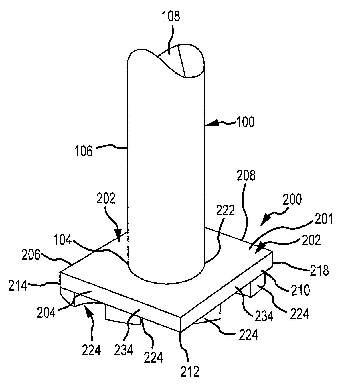
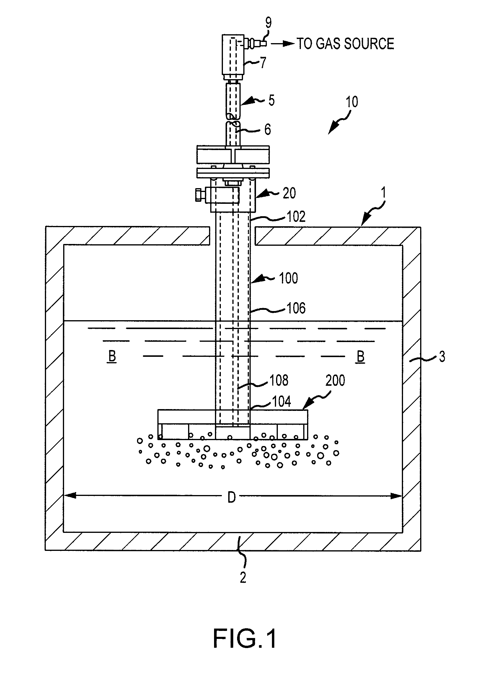
[0021]FIG. 1 shows an exemplary gas-release device 10 according to the invention. Device 10 is adapted to operate in a molten metal bath B contained within a vessel 1. Vessel 1 is provided with a lower wall 2 and side wall 3. Vessel 1 can be provided in a variety of configurations, such as rectangular or cylindrical. In this exemplary embodiment, vessel 1 includes a cylindrical side wall 3 and has an inner diameter D.

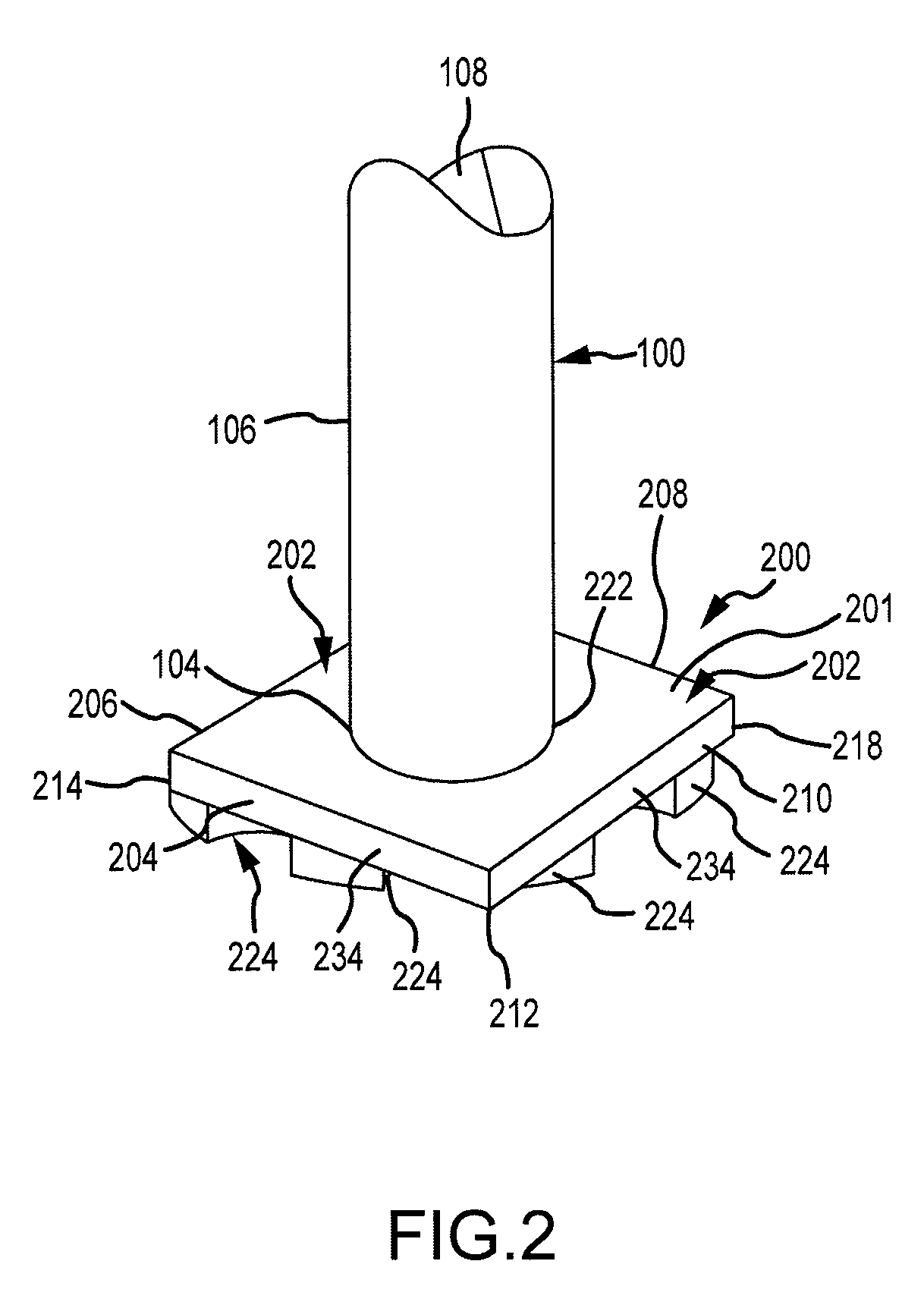
[0022]Device 10, which is preferably a rotary degasser, includes a shaft 100, an impeller 200 and a drive source (not shown). Device 10 preferably also includes a drive shaft 5 and a coupling 20. Shaft 100, impeller 200, and each of the impellers used in the practice of the invention, are preferably made of graphite impregnated with oxidation-resistant solution, although any material capable of being used in a molten metal bath B, such as ceramic, could be used. Oxidation and erosion treatments for graphite parts are practiced commercially, and graphite so treated can b...


PUM

PropertyMeasurementUnit
anglesaaaaaaaaaa
widthaaaaaaaaaa
flow ratesaaaaaaaaaa

Abstract

A device for dispersing gas into molten metal includes an impeller, a drive shaft having a gas-transfer passage therein, and a first end and a second end, and a drive source. The second end of the drive shaft is connected to the impeller and the first end is connected to the drive source. The impeller includes a first portion and a second portion with a plurality of cavities. The first portion covers the second portion to help prevent gas from escaping to the surface without entering the cavities and being mixed with molten metal as the impeller rotates. When gas is transferred through the gas-transfer passage, it exits through the gas-release opening(s) in the bottom of the impeller. At least some of the gas enters the cavities where it is mixed with the molten metal being displaced by the impeller. Also disclosed are impellers that can be used to practice the invention.

Description

BACKGROUND OF THE INVENTIONField of the Invention[0001]The invention relates to dispersing gas into molten metal. More particularly, the invention relates to a device, such as a rotary degasser, having an impeller that efficiently mixes gas into molten metal and efficiently displaces the molten metal / gas mixture. This application claims priority to U.S. Provisional Application No. 61 / 232,384 to Cooper filed on Aug. 7, 2009 and entitled “Rotary Degasser and Rotor Therefor.”Description of the Related Art[0002]As used herein, the term “molten metal” means any metal in liquid form, such as aluminum, copper, iron, zinc and alloys thereof, which is amenable to gas purification or that otherwise has gas mixed with it. The term “gas” means any gas or combination of gases, including argon, nitrogen, chlorine, fluorine, freon, and helium, that are mixed with molten metal.[0003]In the course of processing molten metals it is sometimes necessary to treat the molten metal with gas. For example, ...

Claims


Application Information

Patent Timeline
Patent Type & Authority Patents(United States)
IPC IPC(8): C22B9/05C21C7/00
CPCC21C1/06C22B9/05F27D3/16F27D27/00F01D5/147
Inventor COOPER, PAUL V.
Owner MOLTEN METAL EQUIP INNOVIATIONS LLC
Learn More