
Identification and analysis of source emissions through harmonic phase comparison

a harmonic phase and emission detection technology, applied in the field of signal processing, can solve the problems of difficult detection of electromagnetic radiation from electronic devices, inability to positively associate these emissions with devices in the presence of a noisy electromagnetic background, and the doubt of whether the received emissions are in fact related to the targeted device, so as to reduce the false alarm rate of electronic device sensing systems, increase detection confidence, and reduce false alarms

Active Publication Date: 2013-09-17
NOKOMIS
View PDF24 Cites 21 Cited by
  • Summary
  • Abstract
  • Description
  • Claims
  • Application Information

AI Technical Summary

Benefits of technology

The present invention is a method to detect and identify the source of electronic device emissions. It reduces false alarm rates by analyzing the received spectrum and identifying candidate emission elements based on their frequency and phase relationship with other emissions. This increases the confidence of detection by verifying the relationship between the measured data and a software solution of the known closed-form expression that governs the distribution of emissions within the source.

Problems solved by technology

Any electronic device necessarily emits electromagnetic radiation unintentionally.
However, the ability to detect these emissions and positively associate them with a device in the presence of a noisy electromagnetic background is particularly difficult.
Even when this is achievable, there often remains doubt as to whether the received emissions are in fact related to the targeted device.
In particular, it is difficult to identify a device with a low false alarm rate when in the presence of multiple interferers, or when multiple devices are present.
Further, it is difficult to dissociate identical devices from one another such that accurate geo-location may be performed.

Method used


Image

  • Identification and analysis of source emissions through harmonic phase comparison
  • Identification and analysis of source emissions through harmonic phase comparison
  • Identification and analysis of source emissions through harmonic phase comparison

Examples


Embodiment Construction

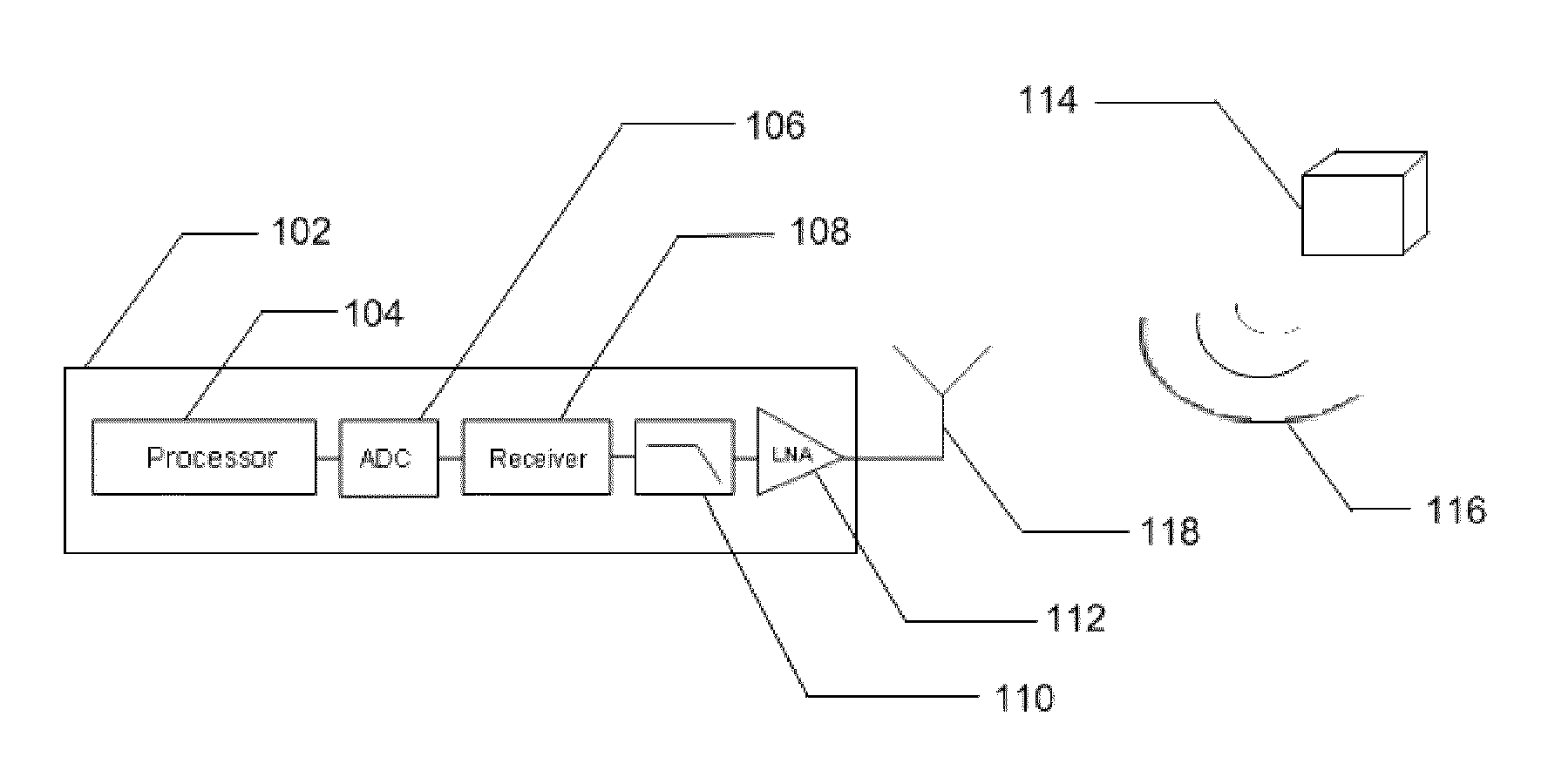
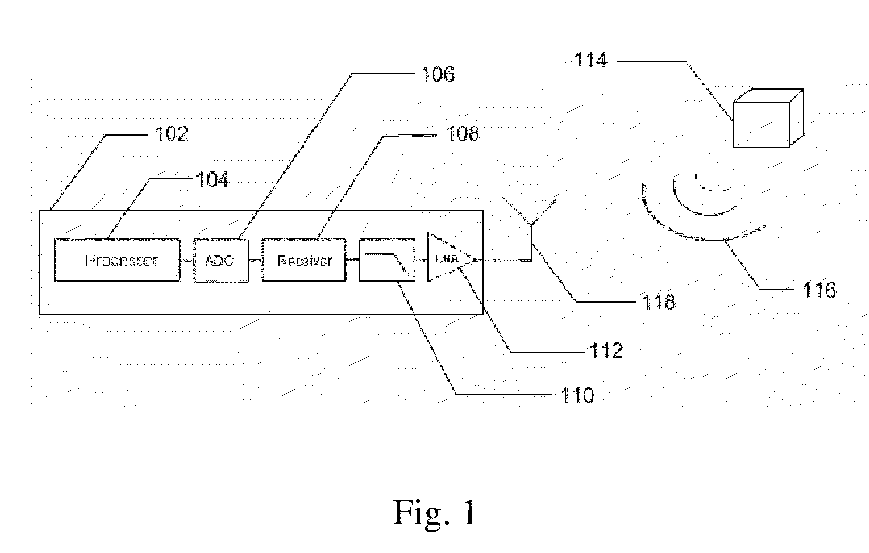
[0093]Referring now to the drawings, in FIG. 1 there is shown a specific embodiment of a system 102 for the detection of source emissions, specifically the detection of unintentional emission from electronic devices. The system 102 is used to capture electromagnetic emissions with the intention of identifying the existence of an electronic device 114. The system detects electromagnetic radiation 116 which radiates unintentionally from a device 114. The radiation 116 is detected through use of an antenna 118. The detected radiation is amplified above the background noise through use of a low noise amplifier 112 to generate a received signal. The received signal is then filtered 110 to prevent signal aliasing and reduce the noise bandwidth of the signal. The signal is then received 108 to reveal the in-phase (I) and quadrature (Q) components and digitized through the use of an analog-to-digital converter 106. The digitized output is analyzed with a processor 104 to reveal the phase an...


PUM


Abstract

The present invention is a signal processing method to significantly improve the detection and identification of source emissions. More particularly, the present invention offers a processing method to reduce the false alarm rate of systems which remotely detect and identify the presence of electronic devices through an analysis of a received spectrum the devices' unintended emissions. The invention identifies candidate emission elements and determines their validity based on a frequency and phase association with other emissions present in the received spectrum. The invention compares the measured phase and frequency data of the emissions with a software solution of the theoretically or empirically derived closed-form expression which governs the phase and frequency distribution of the emissions within the source. Verification of this relationship serves to dramatically increase the confidence of the detection.

Description

CROSS-REFERENCE TO RELATED APPLICATIONS[0001]This application is related to and claims priority from U.S. Provisional patent application titled “Identification and Analysis of Source Emissions through Harmonic Phase Comparison” filed on Oct. 23, 2009 with Ser. No. 61 / 279,605.STATEMENT REGARDING FEDERALLY SPONSORED RESEARCH OR DEVELOPMENT[0002]Not ApplicableREFERENCE TO SEQUENCE LISTING, A TABLE, OR A COMPUTER PROGRAM LISTING COMPACT DISK APPENDIX[0003]Not ApplicableBACKGROUND OF THE INVENTION[0004]The present invention is in the technical field of signal processing. More particularly, the present invention is in the technical field of electromagnetic signal processing. More particularly, the present invention is in the technical field of unintended electromagnetic signal processing for the purposes of detecting, identifying and locating electronic devices.[0005]Any electronic device necessarily emits electromagnetic radiation unintentionally. These emissions are commonly referred to...

Claims


Application Information

Patent Timeline
Patent Type & Authority Patents(United States)
IPC IPC(8): G01S13/88
CPCG01R29/0892G01S7/38G01V3/12G01S13/88G01S7/41
Inventor FREEMAN, STEPHEN DORNKELLER, III, WALTER JOHN
Owner NOKOMIS
Learn More